
An industrial push button panel cutout size comes from the approved mounting drawing for the exact operator, not from its cap diameter or a generic product-family name. Check the opening shape and tolerance, finished panel thickness, anti-rotation features, retaining hardware and rear clearance together before cutting a production panel. A button that enters the hole can still be poorly retained or impossible to wire. This guide explains how an OEM turns the drawing into a fabrication and sample-inspection record without transferring another manufacturer’s dimensions to a LEMA PBS product.
Separate the actuator, bezel, mounting body and hole
A front-view photograph contains several circles, and only one may describe the mounting interface. The visible actuator is the surface an operator presses. The bezel surrounds it. A threaded body or mounting collar passes through the panel. The drawing specifies the opening that accepts that body, sometimes with a flat, keyway or secondary notch. Measuring the largest visible circle therefore does not identify the required hole.
Keep those dimensions in separate fields. Label the front clearance envelope, mounting opening and rear envelope explicitly on your panel layout. The bezel can overlap the opening while the contact block extends sideways behind it. Adjacent operators may clear each other on the front yet interfere through their terminals, clips or cable bends. A complete mounting review follows the whole assembly through the panel.
LEMA’s PBS original includes front and side views with several different dimensions. Treat those views as product-reference information and request the current drawing for the ordered variant. This article intentionally gives no universal PBS hole diameter: a depicted head measurement, a body dimension and a manufacturing cutout are different quantities. Copying one number without its dimension arrows and tolerance is an avoidable purchasing error.
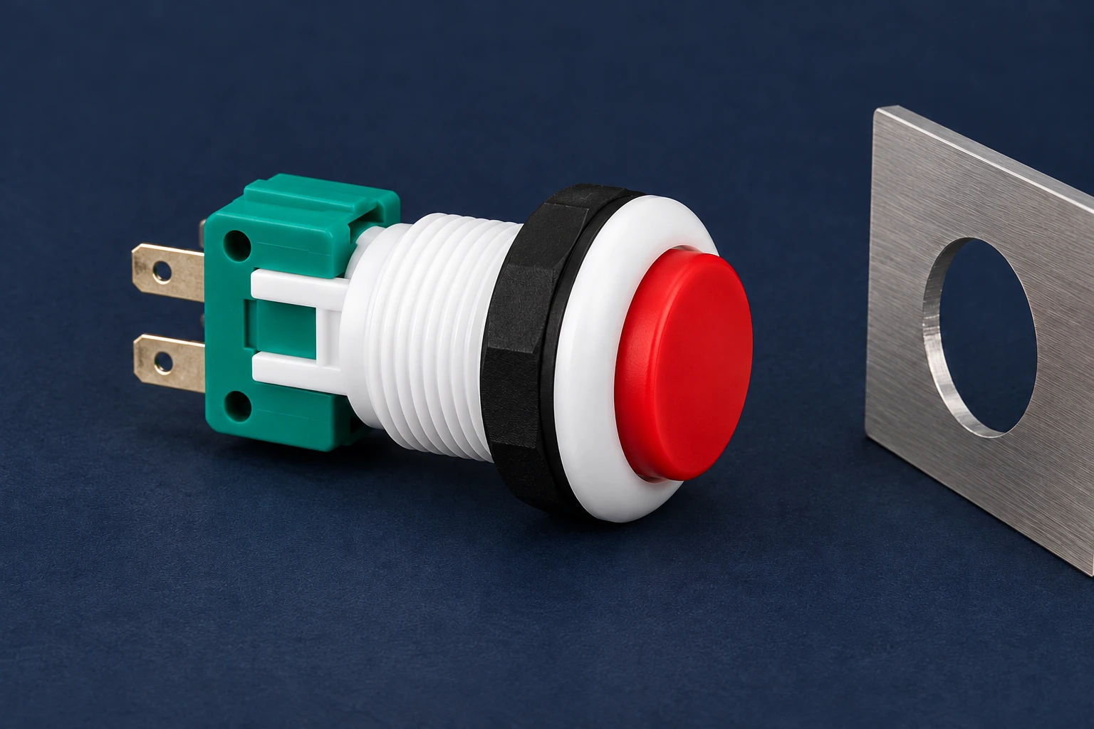
Read the exact variant drawing before choosing a tool
Confirm the part number and drawing revision first. Record whether the drawing covers an assembled operator, an operator alone or a contact component sold separately. Check the units and identify dimensions referenced to the panel surface. If a mounting detail is absent, ask for it before releasing the panel file; a sales photograph is not a fabrication specification.
Next identify the shape. A plain circular hole, a circle with an anti-rotation feature and a rectangular snap-in opening require different fabrication decisions. For a keyed opening, the key orientation belongs on the drawing as well as the key dimensions. For snap-in retention, the permitted panel thickness and opening tolerances must support the latch geometry. Do not convert one mounting style into another by enlarging an opening until the part fits.
Ask how the dimensions apply to the finished panel. Paint, powder coating, plating and burr removal can change the usable opening or clamping stack. Manufacturing and quality teams should agree whether the acceptance measurement occurs before or after finishing. If the supplier provides only nominal dimensions, request the allowed range and the inspection method rather than inventing a tolerance.
A mounting-interface checklist for the panel release
| Field to verify | Evidence to obtain | Problem caught before production |
|---|---|---|
| Opening diameter or shape | Dimensioned mounting detail for the exact operator | Confusing actuator size with the actual cutout |
| Opening tolerance and finishing stage | Approved upper/lower limits and acceptance stage | A coated hole becoming tight or an oversized hole losing support |
| Panel thickness | Permitted finished thickness and full hardware stack | Insufficient thread engagement or failed clip retention |
| Anti-rotation and orientation | Key, flat or notch detail and installed direction | Operator rotation moving terminals or markings |
| Front and rear clearance | Installed envelope plus wiring and service clearance | Contact-block, harness or adjacent-operator interference |
| Fastening and sealing | Specified hardware, assembly method and any tested seal conditions | Damaged plastic, uneven gasket compression or an unproven seal |
This is a qualitative engineering checklist, not a dimensional standard. The limits must come from the selected product’s mounting documentation. IEC 60947-5-1 covers electromechanical control-circuit devices; its publication scope does not establish a universal mounting hole for every push button.
Include panel thickness, hardware and seal compression
The retaining nut has to clamp the finished panel using the intended washers or gaskets. Count every layer in the assembly, including reinforcement plates when present. A decorative faceplate can change the stack even if the main enclosure sheet remains unchanged. If an operator’s threaded section is partly occupied by a bezel or spacer, the remaining usable engagement matters.
Do not solve a loose operator by tightening harder without a specified method. Excessive force can damage a plastic mounting body, distort the panel or alter the operator’s motion. A sample that rotates after normal presses needs an investigation of hole size, anti-rotation geometry and hardware placement. Record the cause instead of accepting an improvised washer arrangement that has never been approved.
Any ingress claim also depends on the tested assembly conditions. A gasket shown in a catalogue picture does not prove the completed enclosure’s protection. Check the actual gasket, panel finish and mounting instructions against the variant documentation. Where exposure is important, retain the supplier’s seal evidence and validate the finished installation under the equipment’s requirements.
Inspect the fabricated opening without forcing a fit
Remove sharp burrs and inspect the edge before inserting the operator. Protect the contact component from metal chips and keep the electrical assembly disconnected during mechanical inspection. Use suitable measuring equipment and record the finished opening in the specified directions. A damaged edge can cut a gasket or stop the bezel seating evenly despite an apparently correct diameter.
A caliper can support an initial dimensional check, but its capability must suit the tolerance being verified. Measure without tilting or excessive jaw force. Repeat the check in different directions when assessing a circular opening, and use the quality team’s agreed method for a keyed shape. The NC BioNetwork caliper lesson demonstrates inside and outside measurement on a vial; it is useful instrument background, not a push-button cutout specification.
If the operator does not enter freely as intended, compare the actual opening, coating and mounting body against the drawing. Do not file a production hole around a single sample and silently change the panel design. If a fit correction is necessary, document the approved dimensional change and repeat the retention review. Keep both the rejected sample measurements and the corrected result.
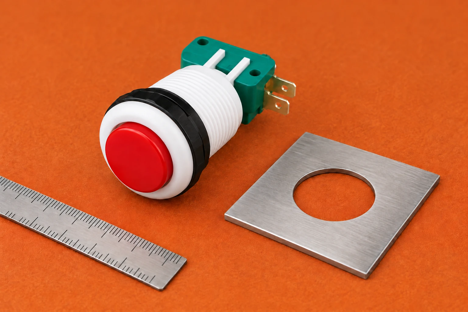
Check rear access before approving the first assembly
Fit the intended contact component and terminal connection in the sample enclosure. Check the space needed to insert and remove a connector, route the wire and operate any retaining clips. Clearance should support assembly and service, not merely accommodate the static outline of an unwired switch. Confirm that the rear harness cannot push the operator sideways or obstruct a neighbouring device.
Operate the button repeatedly while watching the bezel and mounting body. The panel should not flex enough to change the action or loosen the operator. Confirm the intended released and pressed states through the approved electrical test, but keep that test separate from the mechanical fit decision. A button can pass continuity while failing its mounting or sealing requirements.
When the panel belongs to existing equipment, follow the site’s energy-isolation procedure before work. A command button is not an energy-isolating device. This mounting guide does not authorize opening a live control panel or replacing a protective operator with an ordinary one. Retain the equipment manufacturer’s installation and commissioning instructions alongside the mounting record.
Send an RFQ that connects the drawing to the order
Send LEMA the operator variant, panel drawing, finished thickness, cutout detail, retaining-hardware requirement and front/rear clearance needs. Add the command function, electrical duty and environmental conditions so the mechanical choice does not conflict with the control design. Request a matching drawing revision and sample before committing a production tool or laser-cut file.
Use the PBS series product page to identify the relevant family. For the wider selection decision, read industrial push button selection. Compare flush and projected operator clearance and the custom push button RFQ checklist when preparing the complete interface package.
Keep one acceptance record linking the ordered code, drawing revision, panel revision, measured opening, assembled hardware and test results. If a supplier changes the collar, clip, gasket or contact block, reopen the affected fit checks. Preserving this chain makes a repeat order easier to verify and prevents a superficially similar replacement from inheriting approval automatically.
Further learning
This independent educational video provides background for the checks discussed above. It does not identify the terminals of the illustrated LEMA product or replace the equipment manufacturer’s approved procedure.
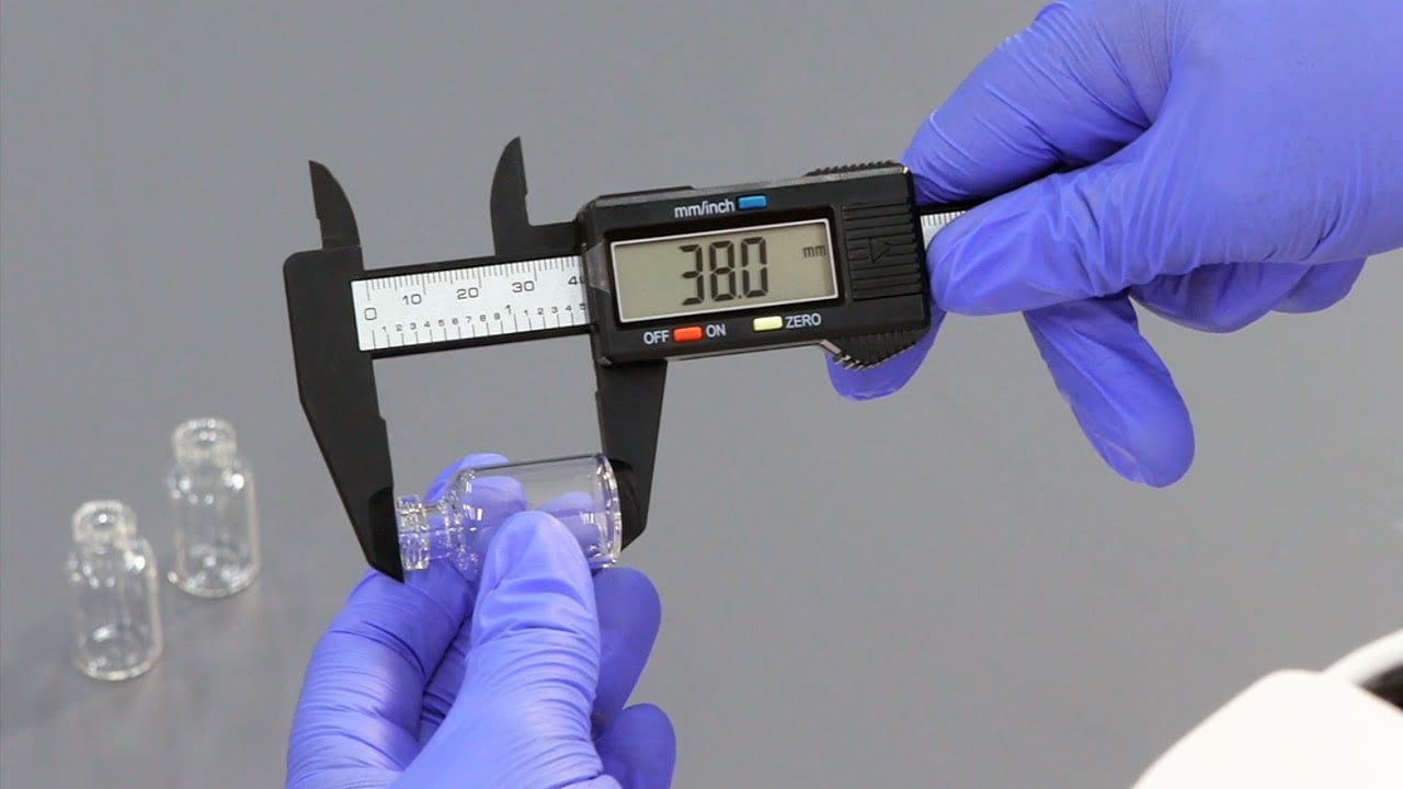
Watch Measuring with a Caliper — BioNetwork
Frequently asked questions
Is the push button cap diameter the hole size?
No. The actuator, bezel and mounting body are separate features. Use the exact variant mounting drawing and its opening tolerance.
Can a nominal 22 mm label define every mounting detail?
No. A nominal size alone does not define cutout tolerance, anti-rotation geometry, panel thickness, hardware or rear clearance.
Should I measure before or after coating?
Use the acceptance stage specified in the approved drawing and process. Confirm the finished opening and clamping stack before assembly approval.
Can I enlarge a tight hole until the sample fits?
Do not make an undocumented production change. Compare the opening and part with the drawing, obtain an approved correction and repeat retention and clearance checks.