
A micro switch test fixture should locate the component consistently, apply the intended actuator motion and observe the electrical event without adding uncontrolled force, movement or circuit effects. Define the measurement before building the fixture: continuity, operating position, release position and force are different questions. Use the exact switch drawing and supported conditions to establish references and limits. A fixture can produce repeatable numbers that are still wrong if it measures from the wrong surface, bends the lever or interprets contact bounce as several independent operations.
Start with the decision the fixture must support
An incoming continuity check asks whether specified terminals change state under defined movement. A travel measurement asks where a defined event occurs relative to a mechanical reference. A force measurement adds the load path, contact point and measurement direction. Life or environmental evaluation adds further conditions and evidence. Do not combine these decisions into one unexplained green light. State what is being measured, which configuration is represented and what result will support the intended acceptance or engineering decision.
The KW7 product page identifies the relevant component family, but the fixture needs the complete candidate variant and controlled documentation. A bare plunger and a roller lever do not share every mechanical reference. If a fixture accommodates multiple variants, use controlled inserts or explicit setups and record which one was used. An operator should not be able to substitute an apparently similar switch and obtain a misleading approval simply because its housing fits between the same two locating blocks.
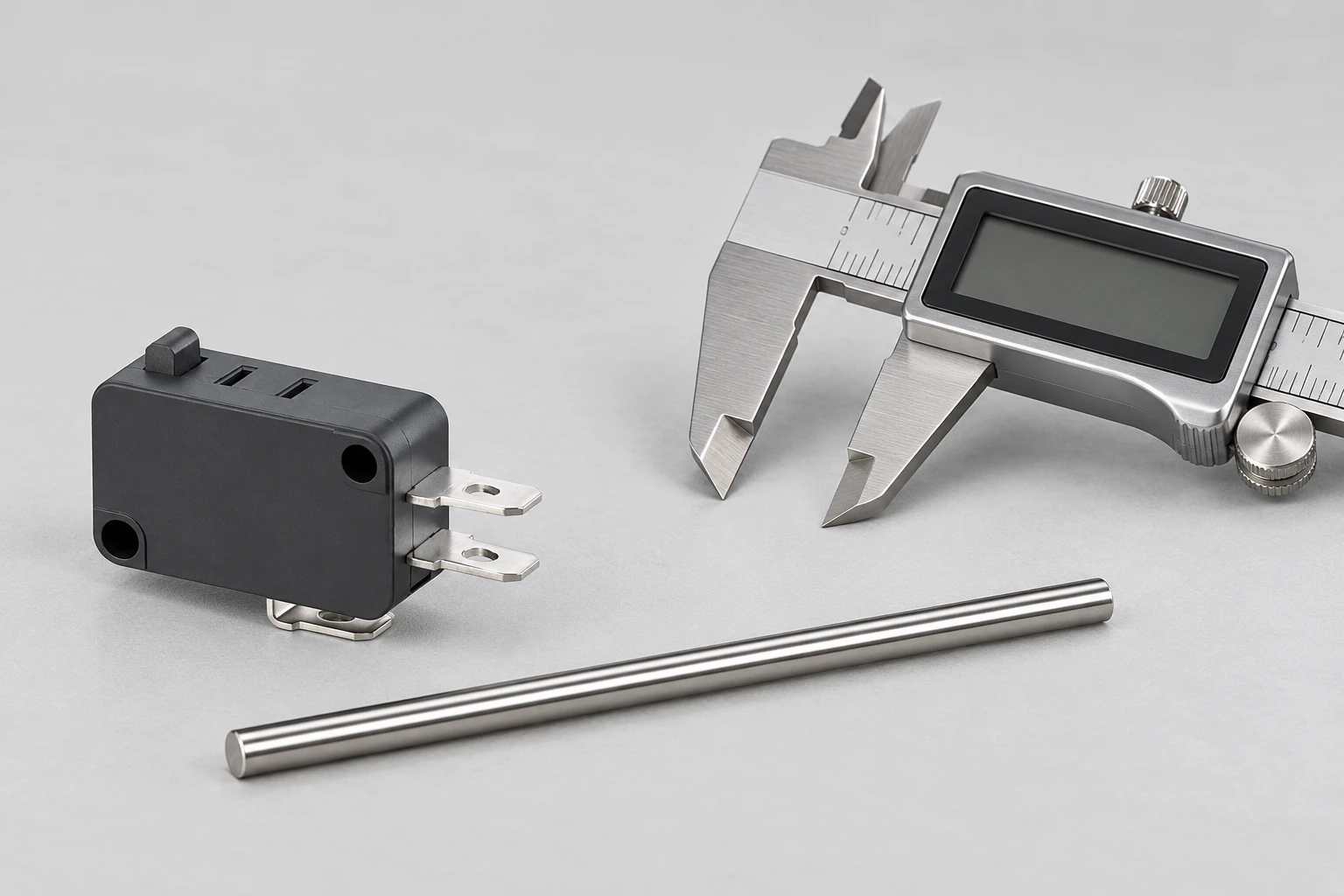
Establish a stable location without distorting the housing
Choose locating features supported by the drawing and intended evaluation. Define the reference surfaces, the constrained directions and the clamping method. The fixture must resist the forces involved in the test while avoiding unintended housing deformation. Clamping harder does not necessarily improve measurement quality. A soft housing, an uneven seat or a trapped piece of debris can change the component’s position or mechanism behavior. Preserve a method for inspecting the seat and checking that the component is fully located.
Treat mounting screws and fixture clamps as separate design choices. The mounting screw torque guide discusses the risk of housing distortion; it does not provide a universal fixture clamp setting. Obtain the supported mounting conditions for the exact variant and evaluate the fixture within its intended purpose. If the fixture deliberately differs from the final assembly, document the difference and why it does not invalidate the decision being made. Convenience alone is not evidence of equivalence.
Define the actuator path and the contact point
The actuator should approach along the intended path, with its position defined relative to the selected references. Record where a tool contacts a lever or roller and what surface it presents to a plunger. A different lever contact point can change the relationship between applied movement and internal operation. A rounded tip can behave differently from a broad flat surface. Check alignment across the actual motion, rather than considering only the starting position shown in a fixture drawing.
The travel terminology guide distinguishes operating and release concepts. Use those definitions consistently when naming fixture outputs, and state how the event is detected. Approach and return measurements require their own direction and reference. Record whether movement is continuous, stepped or reversed, and retain the relevant supported speed. The fixture’s mechanical stop must not become an uncontrolled source of excessive actuator travel when an operator completes a stroke.
Separate electrical observation from mechanical movement
A continuity beeper is useful for certain isolated checks, but its response is not a complete timing measurement. The multimeter testing article provides the separate basic contact-check context. For a fixture that reports operating position, define how the electrical event is detected and related to the movement reading. Meter thresholds, sampling, filtering and control delays can change the reported event. Record them rather than treating the display as a direct view of the mechanism.
Use the electrical conditions required by the evaluation. A high test current may not represent a low-level input application, and an arbitrary low current may not represent a power-load test. Do not energize an unknown circuit to make a fixture easier to read. Establish isolation and the appropriate equipment and competence for the test. Route sensing connections so they do not pull on the switch, contact the actuator or become a hidden mechanical restraint. Inspect connector mating and lead movement as possible contributors to unstable readings.
Record the fixture boundary explicitly
| Boundary | Define | Potential setup contribution |
|---|---|---|
| Location | Reference surfaces and fixture insert | Reseating clearance or trapped debris |
| Clamping | Supported contact points and method | Housing distortion or moving seat |
| Actuation | Tool geometry path and speed | Side force compliance or backlash |
| Electrical event | Terminals circuit and detection rule | Threshold sampling or filtering delay |
| Measurement | Reference units and instrument | Calibration alignment and resolution |
| Record | Specimen fixture and method revisions | Untraceable changes between runs |
This table defines questions to resolve, not model-specific limits. Acceptance limits must come from the applicable requirement, drawing or approved test plan. Keep fixture capability and component requirements as separate records. If the instrument cannot distinguish the changes that matter to the decision, a precise-looking display does not solve the problem. Review the whole path from the physical event to the recorded value, including the reference, sensor, processing and any manual transcription or rounding.
The NIST measurement uncertainty guidance explains why measurement results require consideration of uncertainty. Apply that principle to the fixture’s actual sources of variation. Calibration status is one input; it does not automatically cover alignment, compliance, component reseating or event detection. The uncertainty evaluation must match the measurand and use. Do not quote a general instrument specification as the uncertainty of every result produced by the complete fixture.
Investigate repeatability with deliberate changes
First repeat the measurement without disturbing the setup, then repeat after removing and reseating the same specimen. These exercises reveal different effects. A stable fixed setup can hide sensitivity to location or clamp condition. Where the process involves several operators, include representative operators using the written method. Preserve the sequence and observations rather than averaging all differences into one reassuring value. The question is whether the fixture supports the required decision under normal operating conditions.
If results vary, change one relevant factor at a time when practical. Inspect the seat, tool alignment, target surface, lead restraint and movement method. Compare instrument readings only after confirming that the same event and reference were used. A second instrument does not establish agreement if it observes a different terminal or reports a differently filtered transition. Keep suspect specimens identifiable so an apparent improvement is not simply caused by replacing a difficult component with an easier one.
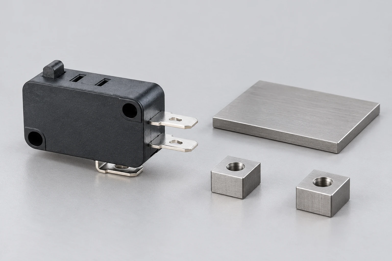
Check compliance, backlash and reversal behavior
A force applied through the fixture can bend the tool, base or mounting arrangement. Some measured movement may then belong to the fixture instead of the actuator. Observe the load path and compare the selected reference with the point where movement is measured. A remote displacement reading can include several structural movements. If that contribution matters to the decision, characterize it or redesign the measurement arrangement. Do not subtract an assumed correction without evidence that it applies under the actual conditions.
Reversal can introduce lost movement or friction effects before the actuator follows the commanded path. This matters when measuring release after an approach stroke. Distinguish commanded movement from observed movement, and allow the method to reveal abnormal sticking or delayed return. Consult the operating speed discussion for the separate speed boundary. A slow manual screw and a driven production mechanism need not produce equivalent observations merely because both eventually change the contact state.
Make the recorded result interpretable later
Store the specimen identity, fixture revision, instrument identity, method revision, setup references and relevant environmental conditions. Record the actual result and its units, together with the event definition and acceptance decision. Retain exceptions, aborted runs and unexplained changes in a form suited to the investigation need. A single pass flag is difficult to interpret when an engineer later discovers that the tool tip, fixture insert or software filtering changed during the evaluation period.
The NIST Engineering Statistics Handbook provides background for measurement-process characterization and data analysis. Use suitable methods for the data and decision rather than adopting a generic sample count. Distinguish exploratory fixture development from a controlled acceptance method. During development, changing a setup can be useful; after release, the same change may require review, revised instructions and evidence that previous and subsequent results remain meaningfully comparable.
Further learning: contact transitions and observation
All About Circuits: Switch Bounce and How to Deal with It Video 1. All About Circuits explains switch bounce and event interpretation. It supports selecting a meaningful electrical observation; it does not approve a KW7 fixture or test threshold.
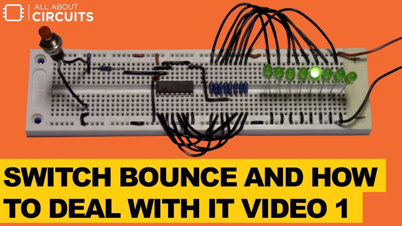
Watch Switch Bounce and How to Deal with It Video 1.
The video supports the electrical observation question: a contact transition may contain behavior that a simple indicator does not describe. It does not specify a KW7 test current, fixture design or acceptance threshold. Define whether the application cares about the first transition, a stable state or the controller’s interpreted event. Preserve that distinction in the fixture output so a change in filtering cannot silently change the meaning of the reported operating point.
Release the method with a usable setup instruction
A practical instruction should identify the variant, fixture insert, reference surfaces, clamp method, actuator tool, motion and electrical connections. Include the checks that show the setup is ready, the conditions that require stopping and the records to retain. Test the instruction with the people expected to use it. Resolve ambiguities before using the method to accept production material. The result should be a supported decision about a defined component characteristic, with the fixture’s own contribution understood well enough for that decision.
Frequently asked questions
Can a continuity beeper measure operating travel?
It can indicate certain contact-state changes but its response may not define the event required for a travel measurement. Specify the event detection and its relationship to the mechanical reading before using the result for acceptance.
Does calibration make the whole fixture accurate?
No. Instrument calibration does not by itself characterize location, alignment, compliance or the event-detection method. Evaluate the complete measurement process for the intended decision.
Should the fixture clamp as tightly as possible?
No. It needs a defined stable location without unsupported housing distortion. Obtain supported mounting conditions and validate the chosen clamp arrangement rather than assuming more force improves the result.
Can one fixture accept several actuator types?
Only with controlled setups that preserve the correct references, path and observation for each type. Record the insert and method used and prevent similar-looking variants from being accepted under the wrong setup.