
Power inlet mating cycle endurance describes how a defined inlet and connector pair performs after repeated connection and disconnection under specified conditions. A cycle count alone cannot tell an equipment buyer whether that pair will remain acceptable in a particular machine. Ask which parts were tested, how a cycle was counted, whether current flowed, what movement and environment were used, and which checks followed the sequence. Keep repeated mating evidence separate from an inlet’s contact rating, a single retention-force result or a general operating-life statement.
For a service-accessible product, the mating pair includes the equipment inlet and the cord connector actually supplied or permitted. Changing either side can change the evidence needed for approval. This guide explains how to review an endurance claim and prepare a useful supplier request. It gives no universal mating-cycle rating for the LEMA IPZ family and does not authorize connecting or disconnecting energized equipment. Testing and servicing must follow the applicable equipment procedure.
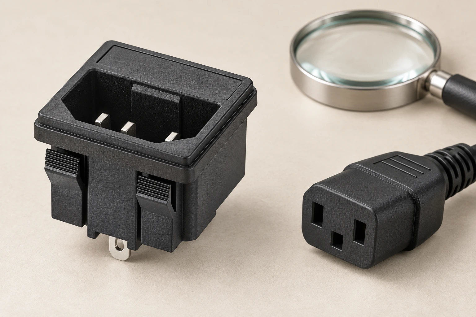
Identify the two sides of the connection
Record the exact inlet variant, mating connector, relevant drawings and approval documentation. Include the connector manufacturer and part number when the equipment specification controls them. A broad description such as an IEC-style inlet is insufficient for comparing endurance reports. The IPZ series AC power socket page is the product reference for discussing the component family. Confirm the actual delivered construction and applicable data instead of extending every family-level statement to every installation.
Also record how the inlet is retained in the equipment and how the user can grip the connector. Panel movement, access restrictions and cable routing can affect the way a person connects and disconnects the pair. These conditions do not automatically form part of a component’s test report. The power inlet panel-cutout guide addresses mounting details that should be resolved before the equipment-level endurance review begins.
Read the scope of a cycle claim
Ask the report to define a complete cycle and any separate insertion or withdrawal counts. Do not assume that two suppliers use the same meaning for operation, stroke or cycle. Identify whether a stated number is a tested sequence, a design target, a minimum contractual requirement or a service-life estimate. Those descriptions answer different questions. A test performed on a small sample is not automatically a guarantee that every production unit will achieve the same service history.
The IEC description of IEC 60320-1:2021 identifies its scope as general requirements for appliance couplers, including incorporated inlets and outlets. Establish the applicable edition and exact report coverage with the supplier or test organization. The public summary does not establish a numeric endurance limit for your variant. Do not borrow a cycle count from another edition, a different coupler type or a marketing page and treat it as an IPZ requirement.
Distinguish mechanical repetition from electrical duty
A sequence performed without current addresses different conditions from a sequence performed under a defined electrical load. Ask exactly when electrical measurements occurred and whether the sequence included make or break events under load. An operating current rating does not, by itself, establish that an inlet can be used as a routine switching device. The responsible equipment designer must define the permitted connection procedure and any required means of disconnecting power.
If the equipment also includes a switch, fuse holder or other accessory, identify which part each life statement describes. A switch mechanism’s operating life is not automatically the endurance of the separable connector interface. Similarly, a cable flex result is not a mating result. Keeping those functions explicit prevents a large number on a family datasheet from being assigned to an untested part of the power path.
Define a representative motion and environment
For a project-specific endurance plan, specify alignment, travel, engagement condition, movement rate and how the specimens are held. Record any cable load or side load that the plan deliberately includes. An uncontrolled operator demonstration may introduce varying angles and forces without documenting them. That makes it difficult to determine whether a later failure comes from the connector pair, the fixture or a changed handling method. Agree the setup with the competent test organization before comparing suppliers.
State the environmental conditioning and whether cleaning, contamination or temperature exposure is included. A dry laboratory sequence does not establish suitability for every installation environment. Avoid silently combining unrelated results, such as a material test on one version and a mating test on another. When test conditions differ from the intended equipment use, record the difference and ask the responsible engineer whether additional evidence is needed. The difference should remain visible in the approval record.
Use an endurance evidence matrix
| Evidence item | Required detail | Common misinterpretation |
|---|---|---|
| Pair identity | Exact inlet and cord-connector variants | Similar shape means equivalent life |
| Cycle definition | Connection, disconnection and count convention | A stroke is always a complete cycle |
| Electrical duty | Current conditions during sequence and checks | Current rating proves switching endurance |
| Setup | Motion, alignment, rate and mounting | A hand demonstration equals a controlled test |
| Acceptance | Applicable measurements and criteria | Continuity alone establishes full suitability |
| Traceability | Samples, interruptions and counterpart changes | Every counted sequence describes the same pair |
This matrix organizes questions; it does not prescribe a standard test or acceptance threshold. Populate it from the applicable report and equipment specification. If a field is missing, request clarification before treating two reports as equivalent. Keep the source of each requirement attached to the record so the test organization can distinguish a standard requirement from a purchaser’s additional qualification condition. No numeric service-life promise follows from the table itself.
Inspect wear without relying on appearance alone
Repeated mating calls for a review of handling as well as the specified final measurements. NASA-STD-8739.4A discusses finite connector life and controlled mating within its aerospace workmanship context. It supports asking how unnecessary handling and contamination are controlled, without establishing a cycle number for an appliance inlet. The IPZ materials, acceptance criteria and application remain subject to their own documentation.
An inspection plan should identify which visible conditions are recorded and which electrical or mechanical checks are required by the governing procedure. A contact that looks clean may still need measurement, while a visible mark requires interpretation against the acceptance criteria. Photograph findings consistently and preserve specimen identity. Do not polish, bend, lubricate or repeatedly remate a questionable specimen simply to make it appear acceptable before the planned examination.
Compare before and after results correctly
Ask for baseline and final measurements made with the documented method, not just a statement that the connector still worked. Depending on the governing specification, the assessment may include contact resistance, retention, damage and other applicable checks. The method and limits must come from the approved test plan. A simple continuity indication does not establish contact heating behavior, and a pull-force result does not establish insulation performance.
The IEC connector retention guide explains the separate question of mating fit and withdrawal evidence. When reading an endurance report, determine whether retention was assessed only initially or also after the specified sequence. Changes need to be evaluated against the applicable criteria. Do not create a universal permissible percentage change from an example report, and do not infer safe performance from a connector that merely remains physically attached.
Keep handling and test history traceable
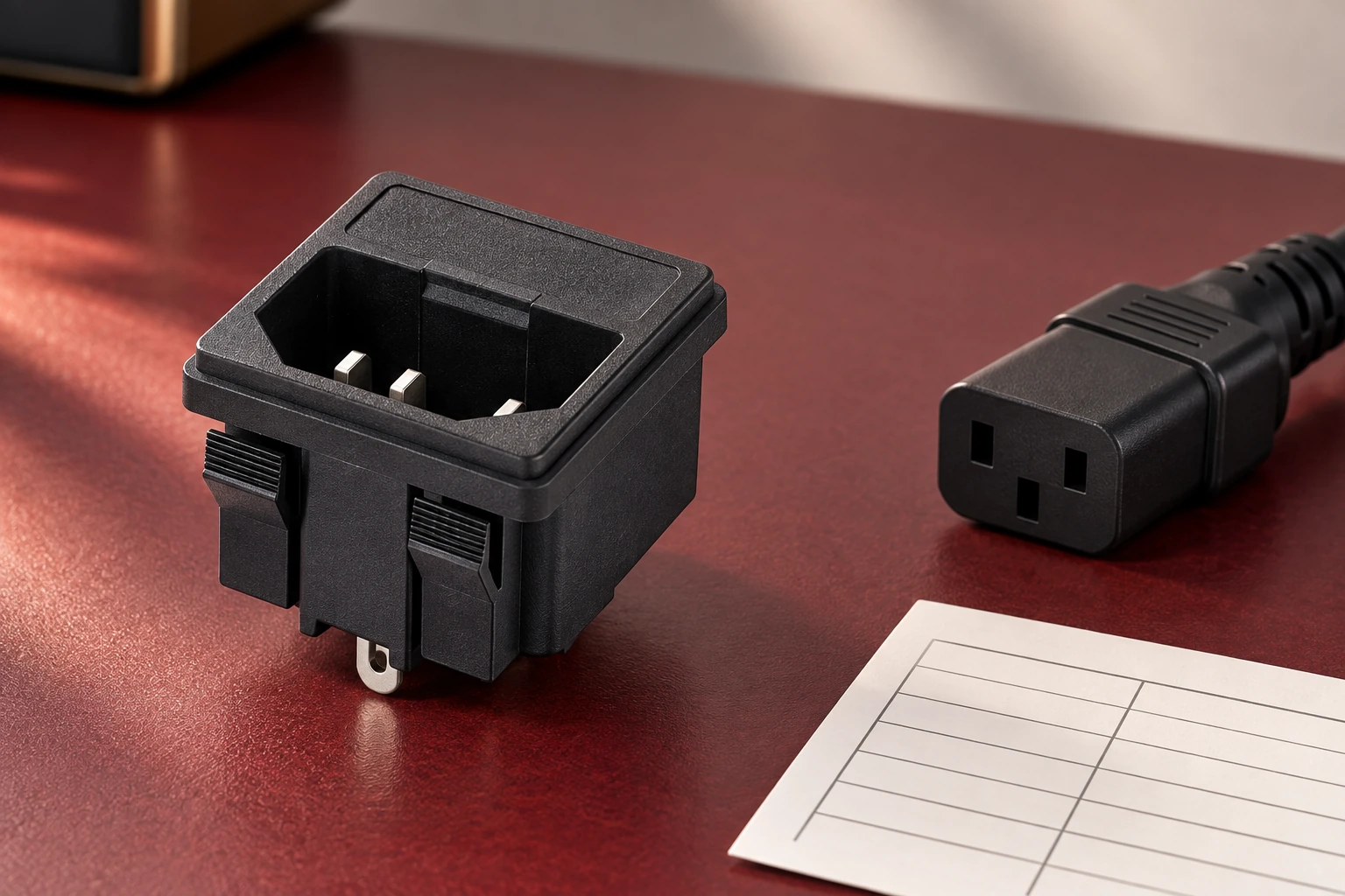
Record the sample origin, configuration and all relevant mating events during preparation and testing. Unrecorded setup operations can make the final count ambiguous. Identify the counterpart used for each specimen and whether it was replaced during the sequence. A fresh connector inserted partway through a test may change what the result represents. Keep any interruption, fixture adjustment or abnormal event in the record so the responsible reviewer can assess its significance.
NASA’s flight connector mating and demating standard description identifies training, records and procedural control within its specialized scope. It is a useful reminder that handling history belongs to connector evidence. Its requirements do not automatically apply to ordinary appliance inlets, and it is not a substitute for the relevant product and equipment documents. Use a traceability system proportionate to the actual project and acceptance plan.
Educational background: why surfaces change with use
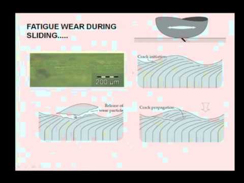
The following NPTEL lecture by Dr. Harish Hirani of IIT Delhi explains wear mechanisms. Use it to understand why repeated movement deserves a controlled assessment rather than a cycle counter alone. It is a general tribology lesson, not a power-inlet test method or evidence for an IPZ endurance rating. The supplier report and the applicable qualification procedure remain the basis for the equipment decision.
nptelhrd: Wear Mechanisms
Translate the result into a purchasing decision
Send the supplier the intended connection frequency, exact mating pair, access arrangement and environmental conditions. Ask for the report number, specimen configuration, sequence definition and acceptance results. Require explanations for family-level life statements when their relationship to repeated mating is unclear. If the equipment permits several cord connectors, decide how each permitted combination is covered. Do not assume a successful result with one counterpart approves every physically similar connector.
Preserve the approved configuration when purchasing replacement parts. The equipment power inlet replacement guide helps organize identity and installation checks, while the inlet temperature-rating guide addresses a separate service condition. Review whether a supplier, material, connector or mounting change affects the endurance evidence. A controlled change decision is more useful than repeating an old cycle number after the tested assembly has changed.
Frequently asked questions
Does an operating-life number automatically mean mating cycles?
No. Confirm the function, exact tested parts, cycle definition and conditions covered by the statement.
Does an endurance report permit unplugging under load?
No. Follow the applicable equipment procedure and the exact connection-duty evidence.
Can one retention-force measurement replace endurance evidence?
No. Initial mating fit and performance after repeated connection address different questions.
Is a universal IPZ mating-cycle rating stated here?
No. Request applicable evidence for the exact inlet, counterpart and intended equipment conditions.