
A micro switch for vending machine equipment is usually a discrete position or interlock input: it can report a service-door state, confirm a vend-mechanism position, or provide a mechanical signal to the controller. It does not independently authorize a payment or replace the machine controller and safety design. Select the switch from its circuit role, actuator geometry, mounting, environment, and service procedure.
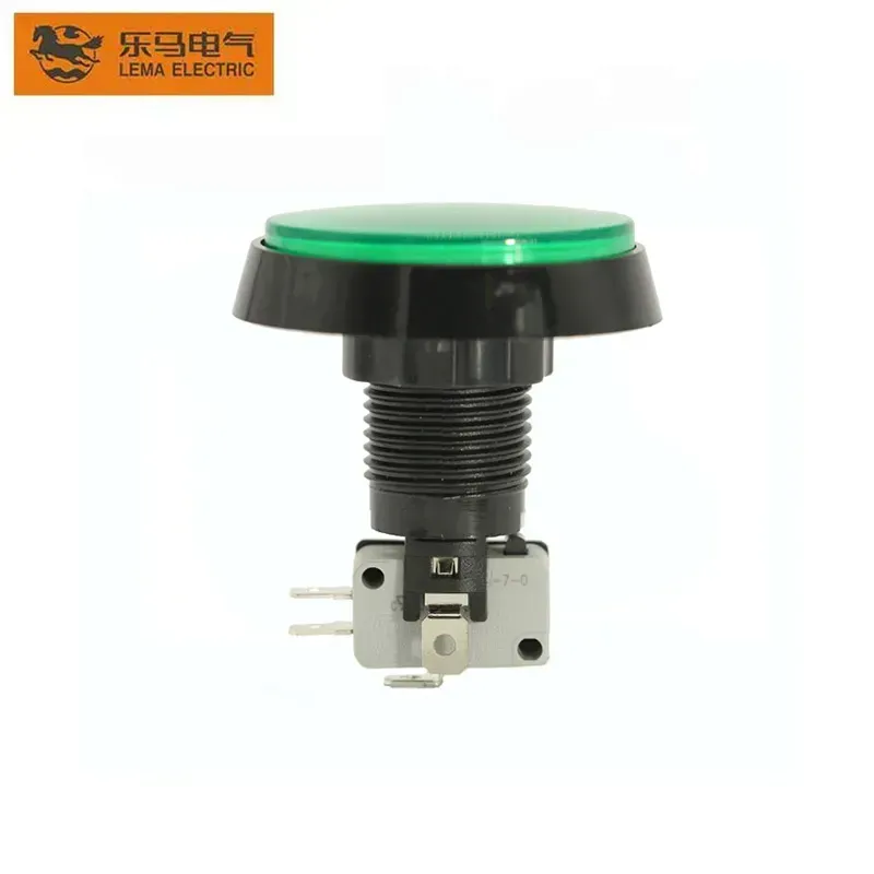
Part 1. What does a micro switch do in a vending machine?
A vending machine contains moving panels, access doors, vend motors, trays, and control electronics. A micro switch can turn one of those physical states into a clear electrical signal. For example, the switch may report that the main door is closed, that a service mechanism reached its home position, or that a mechanical button has been actuated.
Write down the function before selecting a component. “Vending switch” is too broad for an RFQ because a door interlock, a low-voltage controller input, and a vend-mechanism position signal can have different contact states, loads, mounting brackets, and service rules. The original machine schematic remains the source of truth.
| Function | What the switch communicates | Design caution |
|---|---|---|
| Service-door state | Door or panel open/closed condition | Keep service access and safety behavior defined by the machine design |
| Controller input | Mechanism reached/not reached state | Match the controller input circuit and contact logic |
| Vend-position confirmation | Tray, flap, lever, or linkage position | Control actuator travel across tolerance and wear |
| Selection-panel mechanism | Physical selection movement or button state | Do not confuse a mechanical input with payment approval |
Use the LEMA Micro Switch product line for a public category view, then narrow to a specific model only after the circuit and drawing are supplied.
Part 2. Which functions need a door interlock versus a controller input?
A door interlock and a controller input can look similar mechanically, but they serve different electrical functions. A machine may use one circuit to remove or control power when a service door opens and another low-voltage circuit to inform the controller that the door is open. A service manual example for vending equipment describes separate high-voltage and low-voltage door functions, which shows why a buyer must not combine them in an assumed replacement choice.
Decide which circuit owns the action. If the switch belongs to a safety or mains-related interlock, the replacement and validation process is more restrictive than for a low-voltage signal input. A maintenance override, where a design includes one, must be governed by the original equipment procedure and must never become an improvised permanent bypass.
- Door interlock: supports the machine’s defined service-door or panel behavior.
- Door-status input: provides a logic state to software, a display, or service diagnostics.
- Mechanism input: tells the controller that a linkage has completed or left a position.
- Selection input: reports a mechanical user action into the selection/control architecture.
The safety interlock selection method gives a useful general distinction between a snap-action interlock and the wider control system. Apply the actual vending-machine schematic before using that method.
Part 3. Where does the switch fit in payment and vend-mechanism logic?
Payment authorization is normally managed by the payment device and machine controller. A micro switch can provide a mechanical input related to a button, door, coin path, or mechanism, but a contact closure alone does not prove that a payment was valid or that a vend should be authorized. Keep payment rules, inventory logic, and controller diagnostics in their intended systems.
Vend mechanisms may use a switch to confirm home position, flap position, tray movement, or a manual actuator. The control sequence should define what happens when the expected state does not arrive: retry, lockout, operator message, or diagnostic record. The switch selection is only one part of that sequence.
| System area | Appropriate switch role | Not an appropriate claim |
|---|---|---|
| Cashless or coin payment | Possible mechanical input to a defined subsystem | The switch independently approves payment |
| Door service state | Open/closed signal or documented interlock element | Any switch can bypass the service procedure |
| Spiral, tray, or flap | Position confirmation after mechanical movement | One contact diagnoses every vend failure |
| Selection panel | Mechanical button or panel-state input | Contact type can be guessed from appearance |
For button mechanics, see micro switch button operation. It explains the actuator principle; this guide adds the vending-machine circuit and service boundary.
Part 4. Which mechanical and electrical fields define the correct switch?
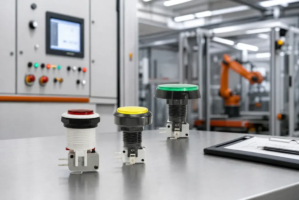
A replacement cannot be selected safely from a photograph alone. Match the function, original contact state, actuator style, mounting holes, terminal layout, circuit load, and environmental exposure. Also confirm whether the switch is mounted to the cabinet, door, payment panel, refrigeration compartment, or a moving vend mechanism.
- Contact form at rest: NO, NC, or SPDT.
- Actual circuit voltage, current, load type, and inrush behavior.
- Actuator type, operating travel, release travel, and allowable overtravel.
- Mounting dimensions, datum surfaces, bracket stiffness, and fastener clearance.
- Terminal type, connector keying, wire routing, and strain relief.
- Temperature, moisture, dust, cleaning exposure, and service-access conditions.
When a cam or linkage needs a roller lever, compare the operating geometry in the roller actuator selection guide. The final selection still needs the original mechanism drawing and a model-specific supplier document.
Part 5. How can teams prevent false door-open and vend-position signals?
False states are often mechanical before they are electronic. A loose bracket, drifting door alignment, worn cam, insufficient overtravel, poor connector retention, or cable force on the terminal can leave the actuator near its transfer point. The controller then receives intermittent open/closed transitions that appear to be a software problem.
Validate the signal with the final door, latch, bracket, harness, and controller input. Cycle both nominal and worst-case positions. Watch the contact transition while the door is closed, opened, shaken, and returned to its intended position. Review the assembly after service access, because a cable or connector can be disturbed during maintenance.
- Set a controlled mounting datum and check door or panel alignment.
- Provide enough travel margin beyond the operating point without damaging the actuator.
- Support the harness so it cannot pull on terminals or alter actuation force.
- Confirm controller debounce or diagnostic rules with the responsible controls team.
- Document the approved maintenance procedure instead of allowing an uncontrolled bypass.
Part 6. What should buyers send before ordering samples or replacements?
Give the supplier enough information to evaluate the whole interface. The original part number is useful, but it is not enough if the machine has been revised or the contact is used differently from the original design. A wiring diagram, photo of the installed mechanism, and measured mounting dimensions reduce avoidable sample cycles.
RFQ input checklist
- Machine function and original part reference, if available
- Original schematic or circuit role, including safe contact state
- Voltage, current, load type, and any inrush or controller-input condition
- NO, NC, or SPDT contact requirement
- Actuator, mounting, terminal, and connector drawings or dimensions
- Door/tray/mechanism travel, environmental exposure, quantity, and sample deadline
Fit Boundary
This selection path suits teams with the original machine documentation that need a position input, door interlock, or mechanism switch review. It is not suitable for guessing a replacement from a photo, bypassing an existing interlock, or treating a discrete switch as a replacement for payment authorization, controller diagnostics, or appliance-level safety validation.
Part 7. How can LEMA support a vending-machine micro-switch inquiry?
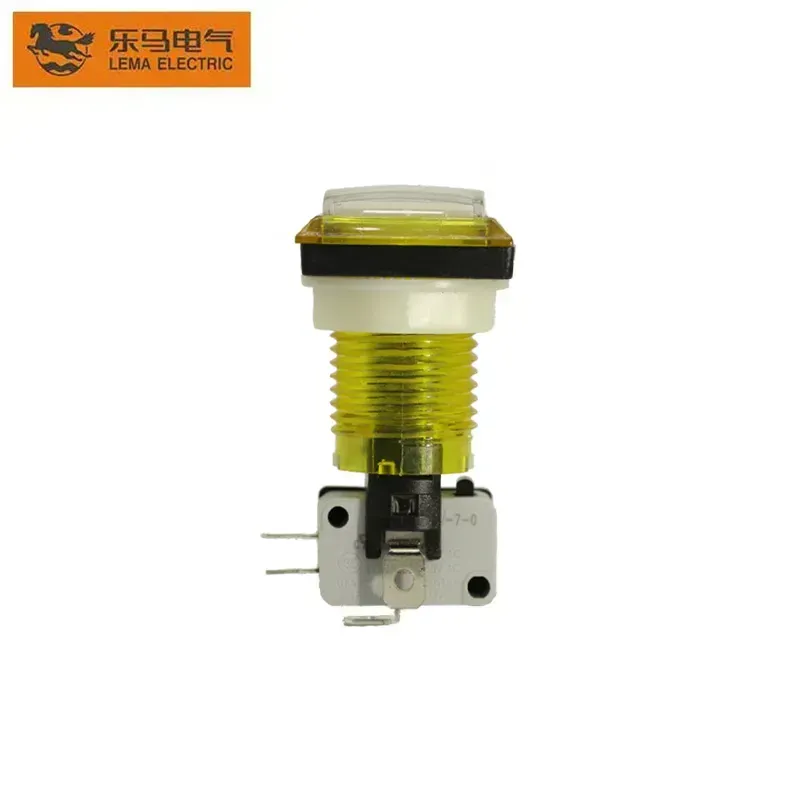
LEMA provides public micro-switch family routes for component inquiry. Start with the KW7 series micro switch when the circuit and mounting concept indicate a compact snap-action form factor. Use the LEMA application support page to frame the application context before a detailed quotation review.
Product recommendation: send the original reference, circuit role, mechanism drawing, terminal layout, and sample quantity for a model-level review. Do not choose a generic series when the machine requires a high-voltage interlock assembly, a specific service override, or an undocumented replacement. Those cases need the OEM documentation first.
Browse the Micro Switch category or request a vending machine switch review with the complete input package.
FAQs
What does a micro switch do in a vending machine?
It usually reports a mechanical position such as a service door, panel, button, tray, or linkage state to a defined circuit or controller input.
Is a vending machine door switch a safety interlock?
It can be part of an interlock design, but the function depends on the original machine architecture. Some machines use separate power-interlock and low-voltage door-status circuits.
Can a micro switch control a vending payment?
It can provide a mechanical input, but payment authorization belongs to the payment and controller system. A contact closure alone does not validate a payment.
What contact form is used for a door-open signal?
The required form depends on the controller and safe-state logic. Confirm whether the original circuit uses NO, NC, or SPDT from the schematic rather than guessing from a replacement listing.
How do teams prevent false door-open messages?
Control bracket alignment, actuator travel, harness strain relief, and connector retention, then validate the signal with the final controller under normal and worst-case mechanical conditions.
What must be checked before replacing a vending micro switch?
Check the original circuit role, contact form, load, actuator, mounting, terminals, connector, environment, and approved service procedure.
When should a door interlock be separated from a controller input?
When the machine architecture requires independent power-control and diagnostic functions. Follow the original schematic and safety design rather than combining those functions in an assumed replacement.