
Plunger Limit Switch decisions begin with the installed mechanism, not a catalogue label. Define the actuator path, circuit duty, environment, mounting, and validation target before requesting a final model review. Similar-looking parts can have different operating windows, terminals, and documented limits.
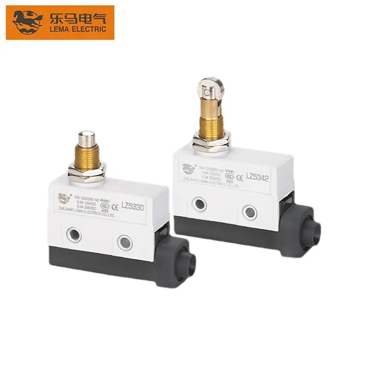
Part 1. Define the position-feedback job
Describe the state that must change, the moving feature that creates it, and the consequence of a late, early, or missing signal. This keeps a mechanical position question separate from assumptions about a particular series.
| Decision field | Input to document | Why it matters |
|---|---|---|
| Function | Free and operated states | Prevents reversed control logic |
| Mechanism | Travel, force, and side load | Controls repeatable actuation |
| Circuit | Voltage, current, load, and inrush | Frames contact review |
| Environment | Contamination, vibration, service access | Frames validation |
Part 2. Map travel and mounting
Put free position, operating position, release, maximum travel, and bracket tolerances on one drawing. The same drawing should identify the approach direction and any side load transferred by a cam, button, linkage, magnet, or stop.
Use the industrial micro switch selection guide when the mechanical interface also needs a broader panel review.
Part 3. Set the environmental boundary
Translate site conditions into exposure inputs: dust, splash, cleaning method, temperature variation, vibration, cable movement, and access for service. A surrounding enclosure does not establish the capability of every component interface inside it.
Record the target exposure and the test method rather than inferring a result from a product family name.
Part 4. Document circuit duty
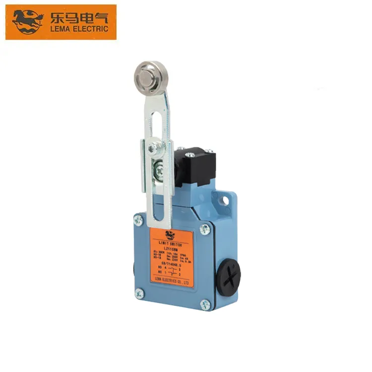
Contact suitability depends on the actual circuit. Capture voltage, current, load type, inrush, switching frequency, and controller input behavior, then compare them with the selected model documentation.
| Validation check | Question | Risk if missed |
|---|---|---|
| Actuation | Does every tolerance stack reach the window? | Missed signal |
| Load | Is electrical duty documented? | Contact degradation |
| Mounting | Is side load controlled? | Operating-point drift |
| Harness | Are terminals protected from pull and abrasion? | Installation failure |
Part 5. Plan validation and fit
Validate production-intent brackets, moving parts, harnesses, and control inputs at nominal and tolerance-extreme conditions. Revisit the plan when the mating part, route, controller, or environment changes.
Fit Boundary
This article supports an OEM selection plan. It does not certify an application, establish a safety function, or prove a model-specific rating, ingress result, or service life.
Part 6. Route a documented inquiry
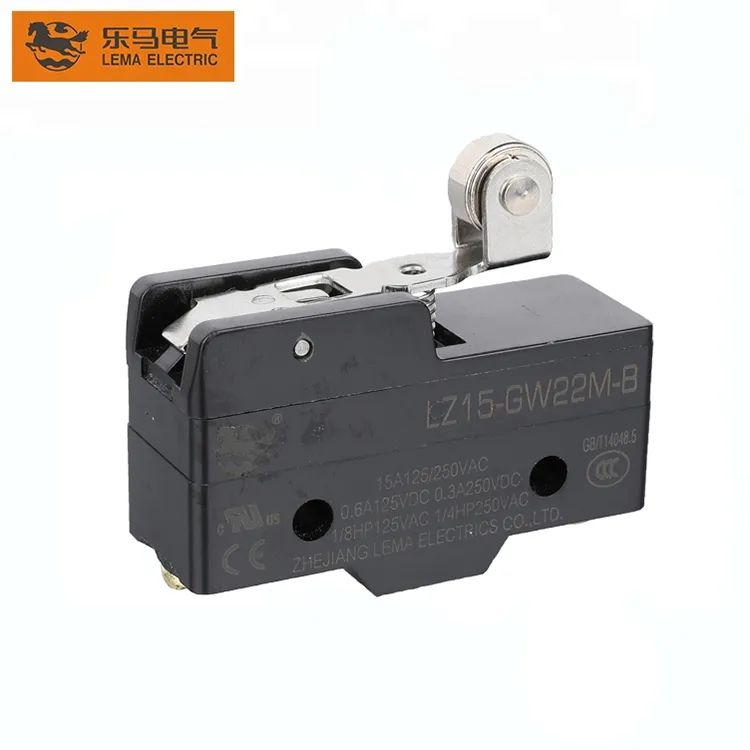
Use the LEMA limit switch inquiry route as a public starting point for a product inquiry. Provide the mechanism, circuit, environment, and validation inputs so the requested model information can be checked against the application.
Product recommendation: request a documented LEMA review after the RFQ fields are complete. Do not choose a part from a generic label, supplied image, or assumed rating.
Send an OEM switch RFQ with the drawing, duty, validation target, volume, and sample timing.
FAQs
What is a plunger limit switch used for?
It converts a short, mostly in-line mechanical press into an electrical state change for position or end-of-travel feedback on machine tools and fixtures.
How do I define plunger stroke for a machine tool?
Record free position, operate point, release, and maximum overtravel on the assembly drawing, including tolerance stack-up from the cam, stop, or moving feature.
Why must mounting stiffness be checked?
A flexible bracket shifts the operating point under load or vibration, so the plunger can miss the travel window even when the drawing looks correct at rest.
How should contact load be documented?
Capture voltage, current, load type, inrush, switching frequency, and controller interface, then compare those values with the selected model documentation.
What contamination checks belong in validation?
Exercise the assembly under the expected dust, splash, cleaning, temperature, and vibration conditions, and confirm the actuator and cable entry still operate reliably.
What belongs in a plunger limit switch RFQ?
Include the mechanism drawing, required contact state, circuit duty, plunger travel, mounting detail, environment, validation target, volume, and sample timing.