
A micro switch for refrigerator equipment normally reports a door or mechanism state to lighting, fan, alarm, or controller logic. It is not automatically a thermostat or defrost controller. OEM teams should define contact logic, actuator travel, mounting, condensation exposure, terminal routing, and the appliance validation plan before approving a switch.
Part 1. What does a refrigerator micro switch do?
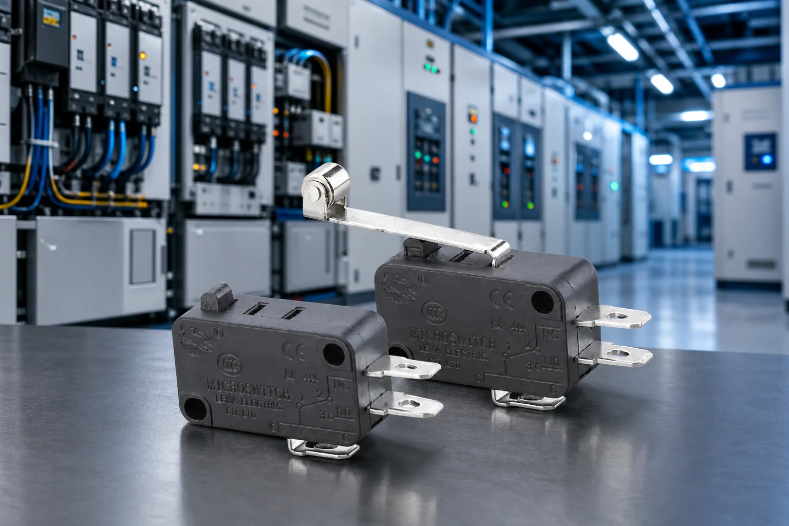
A refrigerator door switch converts door motion into a discrete electrical state. Depending on the appliance architecture, that state can turn an interior light on or off, report an open door to a controller, influence a circulation fan sequence, or trigger a door-open alarm. The micro switch supplies the mechanical state; the appliance controller decides the sequence.
Begin with the exact function. A light-control contact, a low-voltage controller input, and a motor-related circuit can require different contact forms, loads, terminals, and validation. The original schematic is more important than a generic replacement description.
| Function | Switch role | Design boundary |
|---|---|---|
| Interior light | Door-state contact | Confirm actual lamp or driver load |
| Door-open alarm | Input to controller | Controller owns timing and alarm logic |
| Fan sequence | State input or defined circuit contact | Confirm motor/relay interface |
| Defrost control | Possible related input only | Thermostat, sensor, or board may own control |
Use the LEMA Micro Switch product line as the category starting point, then connect the chosen series to a complete appliance drawing.
Part 2. How is a door switch different from a thermostat or defrost control?
A door switch detects a mechanical position. A thermostat or temperature sensor responds to temperature, while a defrost controller coordinates a time, sensor, or programmed control sequence. An appliance may contain all of these components, but they do not perform the same function.
That distinction prevents sourcing errors. A buyer should not specify a micro switch as the primary temperature-control element simply because a search result uses “refrigerator switch.” Identify the schematic block that owns temperature regulation, defrost termination, alarm timing, and door-state sensing before asking for samples.
- Door switch: reports open/closed mechanical state.
- Thermostat or sensor: measures or responds to temperature.
- Control board: applies timing, alarms, fan logic, and defrost sequence.
- Thermal protector: handles its defined protection role.
See the thermostat and interlock boundary guide for the general separation of snap-action interlocks and thermal-control devices.
Part 3. Which circuits use the door-state input?
Door-state logic must match the appliance architecture. In a simple design, the door movement changes the interior-light circuit. In a controller-based design, the same movement can provide a low-voltage input and the board controls light, fan, display, or alarm behavior. Some appliances use multiple contacts or separate sensing paths.
Define what should happen if the door remains open, if a connector becomes disconnected, or if the actuator does not reach its position. Those decisions set the safe contact state and diagnostics. A contact should not be assigned a motor or relay load without checking the actual current, inrush, and circuit protection.
| Specification field | Question | Risk if omitted |
|---|---|---|
| Contact logic | NO, NC, or changeover in the safe state? | Incorrect light or alarm behavior |
| Circuit load | Signal, lamp driver, relay, or other load? | Early contact failure |
| Controller input | What voltage and debounce behavior apply? | False door-open events |
| Failure response | What does the appliance do with an open circuit? | Unclear diagnosis and service |
Part 4. What mechanical and electrical fields define the switch?
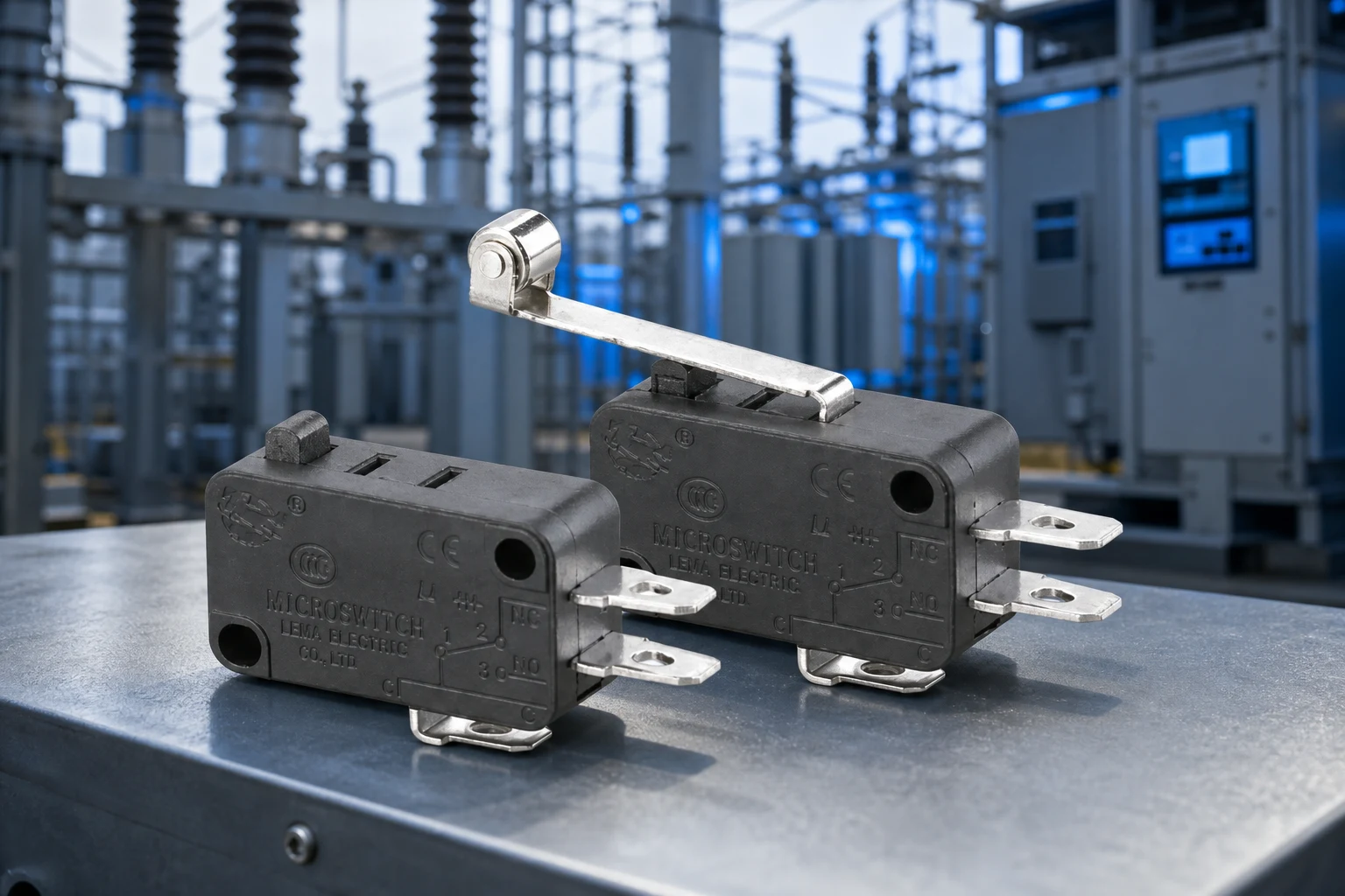
Door switches are often compact, but the interface is not simple. The actuator must receive enough travel across door alignment, hinge tolerance, gasket compression, and cabinet variation. The selected switch must also fit the mounting opening or bracket, terminal space, connector direction, and service access path.
- Required contact state and actual circuit load.
- Actuator style, operating travel, release travel, and allowable overtravel.
- Mounting dimensions, bracket stiffness, and controlled datum surfaces.
- Terminal type, connector keying, wire bend radius, and strain relief.
- Condensation, splash, cleaning, dust, temperature, and service exposure.
Do not choose from appearance alone. Supplier door-switch catalogues demonstrate that actuator, terminal orientation, contact action, and splash options vary even among visually similar components.
Part 5. How should condensation and service access be handled?
Condensation can reach the switch body, terminals, connector, or harness through a door opening, gasket path, drain route, or service operation. Map the actual exposure rather than applying a generic IP term. The installed orientation, cover, terminal shroud, and wire exit all affect the final assembly.
Service access is also a mechanical condition. A technician must be able to inspect or replace the approved part without moving the bracket, pinching a lead, or changing actuator travel. Record the terminal connection and adjustment procedure in the appliance work instruction.
- Check moisture paths at door-open and door-closed conditions.
- Keep connector and terminal access compatible with service steps.
- Support the harness so it does not change the actuator force.
- Verify the input after condensation and cleaning exposure tests.
For broad sealing concepts, use the moisture-resistant switch context, then confirm the selected model’s documented limits.
Part 6. What should OEM teams validate before release?
Validate the switch in the production-intent cabinet, door, hinge, gasket, harness, connector, and controller circuit. Cycle normal and tolerance-limit door positions. Confirm the controller sees the expected state, the light/fan/alarm sequence follows the specification, and the actuator releases after the door closes.
RFQ input checklist
- Door or mechanism function and safe contact state
- Circuit voltage, current, load type, and controller input condition
- Actuator path, travel, mounting drawing, and terminal layout
- Condensation, temperature, cleaning, and service-access conditions
- Validation requirements, sample timing, annual volume, and documentation needs
Fit Boundary
This method suits appliance OEM teams that can provide the door mechanism and schematic. It is not a substitute for temperature-control design, not a way to guess a replacement by photograph, and not evidence that a model meets refrigeration duty without verified documentation.
Part 7. How can LEMA support an appliance inquiry?
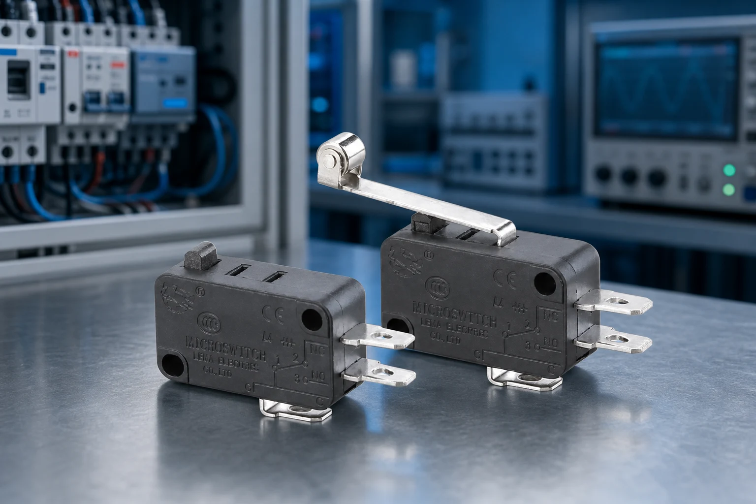
LEMA provides public micro-switch family routes for OEM inquiry. Begin with the KW7 series micro switch when the appliance drawing indicates a compact snap-action approach. Use the LEMA appliance application support route to frame the use case before a model review.
Product recommendation: submit the door movement, circuit, mounting, terminal, and environmental inputs to LEMA. Do not choose a generic series where the project needs a documented sealed door-switch assembly, named appliance approval, or a load outside the model’s quoted scope.
Browse the Micro Switch category or send a refrigerator switch RFQ.
FAQs
What does a refrigerator micro switch do?
It typically senses door position so the cabinet can switch the interior light, fan, or related control inputs when the door opens or closes.
Is a door switch the same as a thermostat?
No. A door switch reports mechanical door state; a thermostat responds to temperature and belongs to a different control function.
Can a switch control the refrigerator light and fan?
Yes when the circuit design routes those loads through the documented contact rating, or when separate poles or relays handle each load.
What causes a refrigerator light to stay on?
Common causes are insufficient door travel on the actuator, a stuck plunger, reversed NO/NC wiring, or a deformed door strike.
How should OEMs select a door switch?
Start from door travel and strike geometry, then confirm contact form, load, terminals, mounting, and temperature or condensation exposure.
Does a refrigerator switch need splash protection?
Specify sealing only when condensation, cleaning, or spill exposure reaches the switch; a cabinet name alone does not create an ingress rating.