
Foot switch electrostatic discharge requirements must distinguish three questions: whether the pedal assembly can generate or retain charge, how any specified grounding or dissipation path is established, and whether the complete control system behaves acceptably during the required discharge tests. A metal enclosure, an ordinary protective-earth connection or an industrial product description does not answer all three. For an OEM buyer, the starting point is an application-specific requirement tied to the exact pedal, cable, connector and controller. Request evidence for that configuration before describing the foot switch as ESD-safe or suitable for an electrostatic protected area.
Decide what the application needs to protect
A pedal used beside exposed electronic assemblies raises different questions from a pedal controlling equipment that must remain stable during an external discharge. In the first case, the ESD program examines charge generation, nearby materials and interactions with sensitive items. In the second, the equipment evaluation examines system response to defined disturbances. Some installations need both assessments, but neither should be substituted for the other.
Describe the work area, operator movement, flooring, footwear, sensitive products and control sequence. Identify whether the pedal is moved between stations, cleaned frequently or placed on different floor surfaces. Record where the cable and connector run relative to the work area. These practical details determine which assembly and operating state the evidence needs to represent. A laboratory result with another cable or surface may leave an important part of the application unassessed.
Das LF-Serie Fußschalter is a reference for pedal construction and configurable wiring. Its general product description does not establish an ESD material classification, a dissipative path or immunity of a finished machine. Ask about the exact quoted assembly and available supporting reports. Where no applicable evidence exists, retain the requirement as unresolved instead of turning a supplier’s broad suitability statement into a verified claim.
Separate charge control from electrical safety
Protective earthing and static-charge control have different purposes and may involve different verification methods. Their relationship must be designed correctly within the equipment. Do not add a wire, resistor or conductive coating to a pedal based on a generic internet diagram. An improvised modification can affect electrical safety, mechanical integrity, signal behavior or the assumptions used in the original assembly evaluation.
Das EOS/ESD Association overview introduces why static control matters across industrial processes. Its material is useful background for defining the problem, but it does not assign an ESD rating to LF pedals. The organization’s basic control procedures and materials guidance also discusses personnel, equipment and production aids. Use that framework to ask how the pedal fits the existing program.
A protective-earth continuity result, where applicable, establishes only the property measured under the selected method. It does not by itself classify every tread surface, confirm operator charge control or demonstrate controller immunity. Equally, a static-control resistance measurement is not a substitute for electrical-safety verification. Define each acceptance question separately and have the responsible specialists agree on the required records.
Review the complete pedal assembly
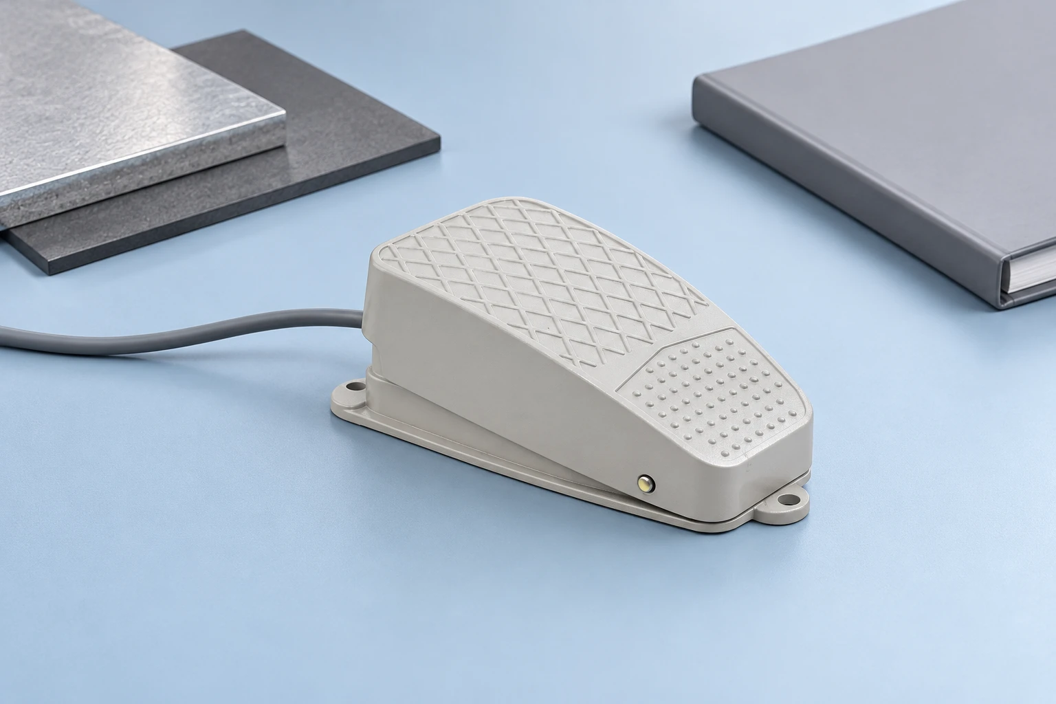
Begin with the housing and tread materials, including coatings and inserts. Color and visible texture do not establish whether a surface is conductive, dissipative or insulating. Ask for the actual material identification and any test evidence applicable to the finished part. A resin datasheet may be relevant, but molded geometry, surface treatment, contamination and the method of measurement can affect what the assembly-level result means.
Next, examine mounting features and any intended electrical path between conductive parts. Fasteners, paint and isolation features can influence continuity. The record should show which interfaces are intended to conduct and which are intended to insulate. Avoid assuming that two metal-looking surfaces are electrically connected simply because a drawing shows them touching. The required relationship must be supported by the design and its verification.
Finally, include the cable, strain relief, connector and mating equipment. A cable shield, protective conductor and signal return are not interchangeable labels. Identify their functions on the approved drawing, then request the evidence appropriate to each. For connector specification background, refer to the foot switch connector guide. Add the ESD-related requirements to the existing electrical and mechanical requirements rather than replacing them.
Specify measurements with their conditions
An unexplained resistance number is difficult to use. Ask what surfaces or points were measured, which method and instrument were used, how the assembly was supported, and what environmental conditioning applied. Include sample identity, preparation and the state of any cable or connector. A report should make clear whether it describes a material sample, an isolated component or the assembled pedal in its installed configuration.
The applicable ESD program or standard should determine the measurement method and acceptance criteria. This guide deliberately does not assign a universal resistance range to every pedal. Different functions require different evidence, and the responsible program owner must select criteria that fit the application. Copying a limit intended for a work surface or footwear system onto a foot-switch housing can create a false sense of compliance.
Define how routine verification relates to initial qualification. A production check may confirm a controlled property, but it does not automatically reproduce a full design assessment. State what will be checked on deliveries, what requires periodic review and what changes trigger requalification. This distinction helps purchasing teams ask for meaningful evidence without requesting an unrelated test certificate for every shipment.
Use an assembly evidence checklist
| Requirement | Applicable evidence | What it does not establish |
|---|---|---|
| Tread and housing | Identified material and relevant finished-part assessment | Color or texture does not classify ESD behavior |
| Conductive interfaces | Defined assembly path and appropriate verification | Metal appearance does not prove continuity |
| Kabel und Stecker | Controlled drawing and function of each conductor | Shield, signal return and protective earth are not interchangeable |
| Workplace interaction | Review within the actual ESD program | Pedal contact with floor does not qualify personnel grounding |
| Equipment immunity | Applicable complete-system evaluation | Pedal material evidence does not establish controller response |
Treat the checklist as a starting point for the application review. Replace each broad item with the actual drawing reference, method and acceptance decision. Do not mark a row complete simply because a supplier attaches a document containing the letters ESD. Check the specimen identity and scope, then determine whether the reported result closes the specific requirement.
Evaluate system behavior independently
A control system can experience a false input, loss of communication, reset or other disturbance even when the pedal’s mechanical contacts remain serviceable. System assessment therefore needs the controller, cable routing, interface and operating states that matter to the equipment. A pedal-only material test cannot demonstrate the immunity of that complete arrangement.
The responsible test plan should define the applicable discharge method, locations, levels, operating modes and performance criteria. Qualified personnel must select those details from the equipment requirements and relevant standards. This guide does not provide a do-it-yourself discharge procedure. Record observed behavior, recovery requirements and any unacceptable response, rather than reporting only that the equipment still switched on after testing.
Distinguish a discharge-related event from ordinary contact behavior. The industrial foot switch troubleshooting guide helps organize contact, cable and control-input checks. An intermittent signal should not be attributed to static electricity without evidence of the event and its relationship to the symptom. Mechanical movement, cable damage and controller settings can produce observations that require their own investigation.
Include operator and floor interactions
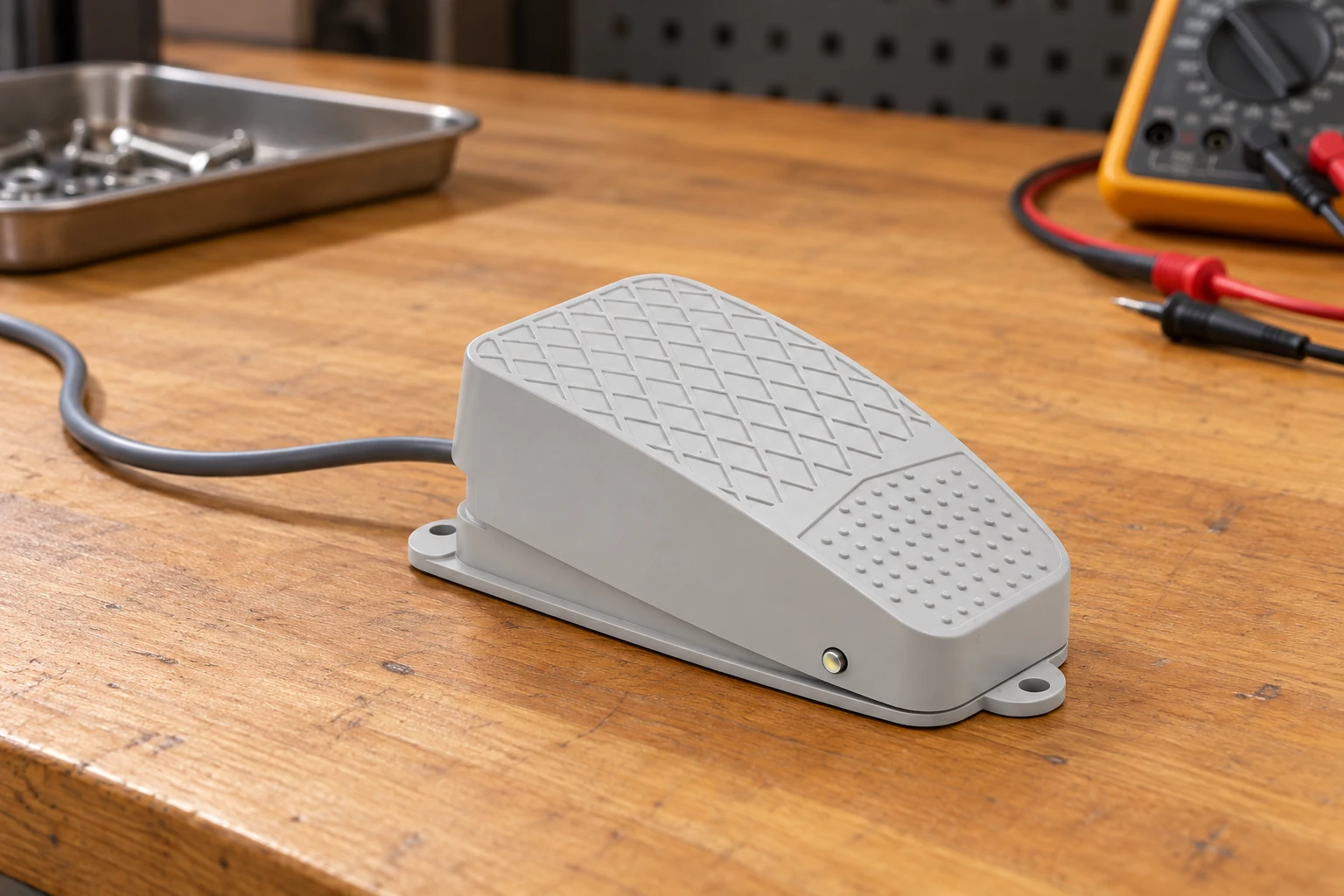
A pedal is operated through footwear and commonly rests on a floor, so it belongs in the workplace interaction review. That does not mean it can be used as a substitute for approved personnel-grounding controls. The ESD program must determine how operators and equipment are managed, including any limitations of the selected flooring and footwear system. A pedal touching the floor does not automatically create a defined or reliable dissipation path.
Consider movement between stations, sliding, rocking and changes in support surface. These can alter both the mechanical task and the electrical relationships assumed during qualification. The foot switch mounting stability guide covers the mechanical side of this problem. Where a fixed arrangement forms part of the ESD assessment, document that arrangement so operators do not unknowingly defeat it by relocating the pedal.
Cleaning and wear also deserve attention. A surface coating, detergent residue, replacement tread or different mounting hardware can change a property relevant to the control program. Establish approved maintenance materials and the conditions that require another check. Do not spray a generic anti-static product onto a pedal to solve an unexplained fault; compatibility, electrical safety and the resulting property would all need appropriate evaluation.
Use educational measurements in the right context
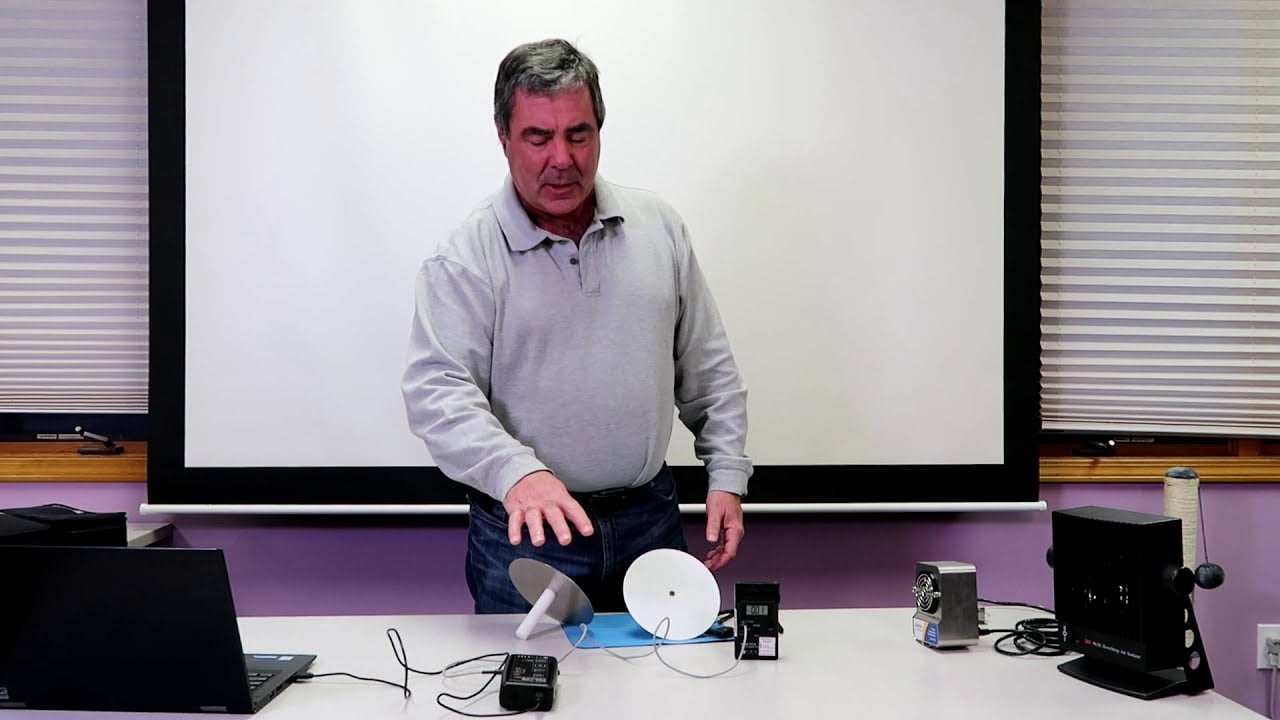
The following EOS/ESD Association video explains tribocharging and electric fields. It provides background for understanding why materials and interactions matter when assessing production equipment. It is not a foot-switch qualification report, a test instruction for the LF series or proof that a particular cable arrangement meets a system requirement. Use it to support discussion with the ESD program owner, while retaining the application-specific methods and evidence as the basis for acceptance.
EOS/ESD Association, Inc.: Tribocharging and Electric Fields
Watch Tribocharging and Electric Fields.
Prepare an RFQ that prevents ambiguous claims
Specify the pedal action, contact requirements, cable and connector first, then add the ESD environment and evidence requirements. Identify whether the request concerns material properties, installed continuity, charge-generation control, system immunity or a combination. Attach the application drawing and state who owns the final equipment assessment. A clear scope lets suppliers disclose limitations and propose alternatives before samples are ordered.
Request controlled identification for any report, material declaration or approved process. Ensure that substitutions affecting the housing, coating, cable, connector or assembly method are communicated before delivery. Keep the accepted configuration connected to its purchase record and sample approval. An otherwise identical-looking pedal may require review if one of those controlled elements changes.
When evidence is incomplete, document what remains unknown and choose an appropriate next action: further assessment, another configuration or a different device. Do not conceal the limitation behind an ESD-safe marketing label. A useful procurement decision states exactly which requirement is supported, under which conditions, and which responsibilities remain with the equipment and ESD-program owners.
For the overall pedal specification, use the Handbuch zur Auswahl eines elektrischen Fußschalters. Add the application-specific evidence above to the normal mechanical and electrical requirements.
Häufig gestellte Fragen
Does a metal foot pedal automatically qualify as ESD-safe?
No. Material identity, interfaces, coatings, grounding arrangements and intended use need applicable evidence for the complete assembly.
Does protective earth continuity prove ESD immunity?
No. Electrical-safety continuity, charge-control properties and complete-system disturbance response are separate acceptance questions.
Can a pedal replace approved personnel-grounding controls?
Do not assume that role. The responsible ESD program must define and verify operator and equipment controls for the actual workplace.
Is LF assigned an ESD rating in this guide?
No. LF is a product reference. Request applicable evidence for the exact pedal, cable, connector and equipment arrangement before making a claim.