CENTRE D’ACTUALITÉS LEMA

Actualités et blog

Centre d’actualités

Micro Switch Terminal Coating Thickness Report: What Buyers Should Check
Blogue LEMA Électrique

Micro Switch Terminal Coating Thickness Report: What Buyers Should Check

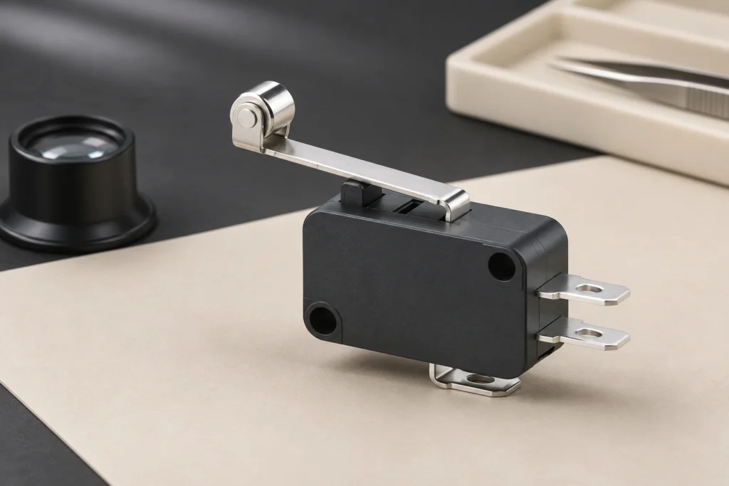
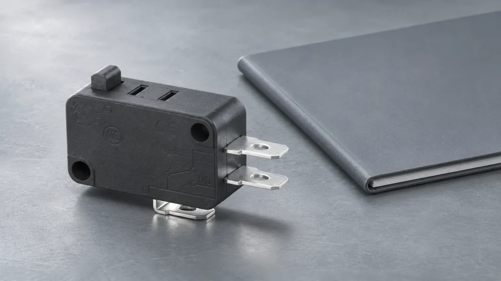
A micro switch terminal coating thickness report is useful only when it identifies the ordered switch, the external terminal finish, the measured locations and the agreed acceptance requirement. A thickness number without that context cannot approve a shipment. First confirm that the terminal is coated and obtain the coating specification; a silver-colored terminal does not identify its material or layer thickness. For buyers reviewing the Lemaele KW7 family, this guide explains how to request a usable report, question an unsuitable measurement and record a defensible disposition without assuming a coating system that the product page does not establish.Define the external-terminal question before ordering a testKeep external connection terminals separate from the internal switching contacts. A report on an accessible solder or quick-connect terminal does not describe the hidden contact interface. Internal contact material, contact resistance, solderability and terminal coating thickness are different evidence items. Decide which one the purchase specification actually requires before sending parts to a laboratory.The KW7 series product page provides a starting point for model selection, but it is not a terminal coating certificate for a particular shipment. Ask Lemaele to identify the exact variant, terminal option, drawing revision and any agreed surface-finish requirement. If no finish specification exists, a laboratory measurement may characterize a sample, but cannot establish a missing contractual acceptance limit.Read the report as a traceable recordStart with the sample identity: supplier, switch order code, purchase order, shipment or production lot and the person who selected the specimens. The laboratory should identify what it received and whether the switches were complete, sectioned or supplied as loose terminals. Loose production coupons can be useful, but their relationship to the delivered switches must be documented rather...

Lire la suite
Limit Switch Mounting Datums and Measurement Uncertainty: Report Review
Blogue LEMA Électrique

Limit Switch Mounting Datums and Measurement Uncertainty: Report Review

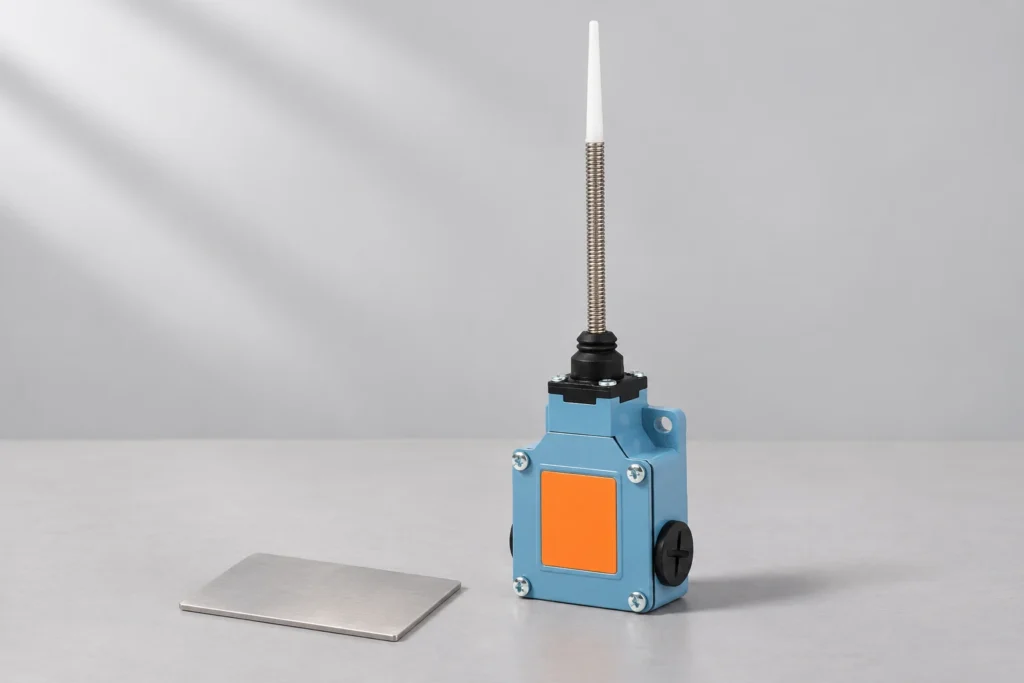
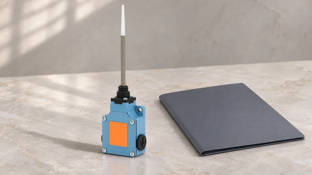
Limit switch mounting datum measurement uncertainty matters when a dimensional report is used to decide whether an ordered switch will locate correctly on its bracket. Define the drawing feature, datum reference and mounting configuration before comparing numbers. A calibrated instrument alone cannot establish that the correct surfaces were measured or that the result supports acceptance. This guide explains how buyers can review a mounting-geometry report, request a useful uncertainty statement and resolve conflicting measurements without inventing a tolerance. It concerns inspection evidence for the supplied component; switching accuracy, installed repeatability and machine safety require their own assessments.Define the mounting question before requesting a reportBegin with the approved switch configuration and bracket drawing. Identify whether the concern involves a hole location, seating surface, spacing, orientation or another drawing characteristic. “Check the mounting dimensions” is too broad to tell a laboratory which result matters. Give the feature a drawing reference and explain the assembly decision that the measurement is intended to support.The Lemaele LZ1 series limit switch is the product reference used here. The pictured blue housing and spring actuator identify one visible configuration, not every available mounting arrangement. The public page does not establish a project-specific datum scheme, hole-position tolerance or measurement uncertainty. Obtain the relevant controlled drawing and confirm that it represents the supplied variant before commissioning a report.Distinguish the datum from the physical setupA datum reference on a drawing provides the framework in which specified geometry is evaluated. The inspection setup must realize that framework using the appropriate features and method. A housing resting on a convenient face may not represent its intended mounting condition. Ask the inspector to identify the actual supporting and locating features and describe how...

Lire la suite
Push Button Cap Molding Flash Inspection: Edges, Fit and Evidence
Blogue LEMA Électrique

Push Button Cap Molding Flash Inspection: Edges, Fit and Evidence

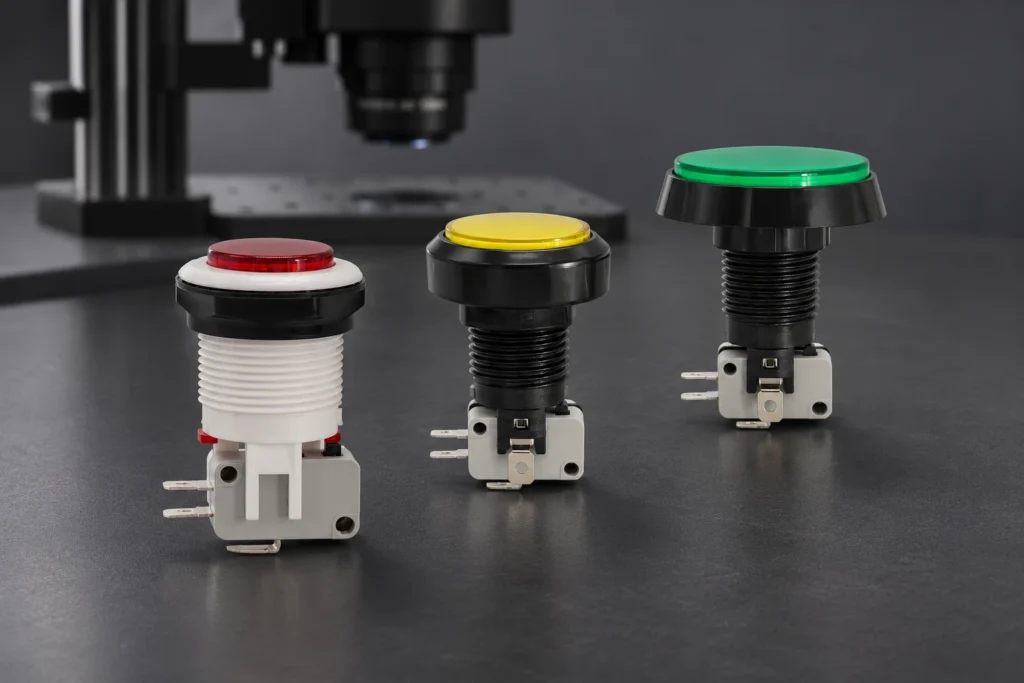
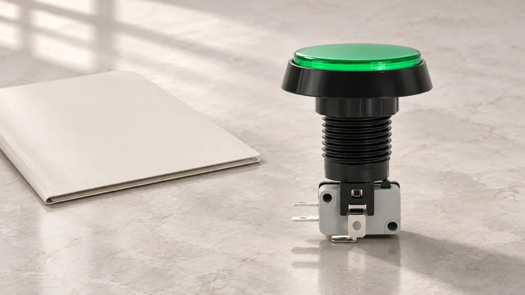
Push button cap molding flash inspection should distinguish excess material from an ordinary parting witness, then evaluate the affected edge against the approved appearance and functional requirements. A visible line is not automatically a reject, and a neat photograph cannot prove that the cap moves freely in its installed arrangement. Identify the ordered button, record the location and extent of the suspected flash, and obtain a supplier disposition before trimming it. This guide gives buyers a practical way to collect edge photographs, compare retained samples and ask the right questions without guessing the cap resin, mold construction or allowable flash dimensions.Identify the cap and the inspection questionStart with the ordered button variant, cap color, illumination option and drawing revision. Give each inspected sample a unique identity. The edge being assessed may belong to the cap, its surrounding collar or another molded part, and those locations have different functions. Label the feature on an overview photograph before requesting a close examination so the supplier can recognize the exact surface.The Lemaele PBS series push button is the product reference for this guide. The family includes different colors and options, so the photograph of one assembly is not a universal appearance master. The public product reference does not identify a cap resin grade, molding process setting or flash tolerance. Ask the supplier for the applicable controlled requirement rather than importing a generic limit from an unrelated molded component.Separate a witness line from excess materialA parting witness can show where tooling surfaces meet, while flash involves material extending beyond the intended molded shape. Do not classify a feature solely from a shadow in one image. Change the lighting and viewing direction, keep the sample...

Lire la suite
Toggle Switch Bushing Thread Pitch: Verify Before Ordering Nuts
Blogue LEMA Électrique

Toggle Switch Bushing Thread Pitch: Verify Before Ordering Nuts

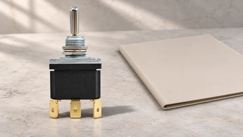
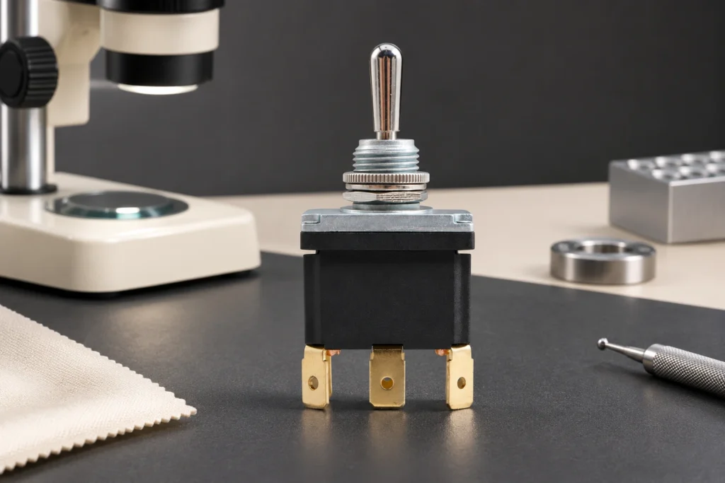
Toggle switch mounting bushing thread pitch verification starts with the complete thread designation on the approved drawing, followed by a suitable inspection of the actual supplied bushing and mounting nut. Outside diameter alone cannot establish compatibility. A nut that turns briefly can still be the wrong thread. Confirm the ordered switch variant, units, pitch and fit requirements before approving replacement hardware. This guide explains a purchasing and inspection workflow for matching nuts to a panel-mounted switch, including what a pitch gauge can establish, what it leaves unresolved, and which records help a supplier investigate a mismatch without forcing the assembly.Separate thread identification from installation approvalThread identification answers a specific question: which thread is specified and does the inspected component match it? Installation approval asks additional questions about the panel, washers, engagement, tightening method and retention. Keep these decisions separate. Identifying a matching pitch does not show that a different nut has the correct height, bearing surface or available engagement for the finished control panel.The Lemaele LT3230C toggle switch provides the product reference for this discussion. Its visible metal lever, threaded mounting bushing and spade terminals identify the assembly being discussed. A photograph does not establish the thread designation, pitch tolerance or mounting torque. Obtain the controlled drawing and the supplier-approved hardware list for the exact order before selecting a gauge or purchasing substitute nuts.Read the full drawing callout before measuringCapture the drawing number, revision and complete thread callout in the inspection request. Preserve every part of the designation rather than transcribing only the leading diameter. Identify the unit system and whether the pitch is expressed as distance between corresponding thread points or as threads per unit length. Ask the supplier...

Lire la suite
Illuminated Push Button Cap Luminance Uniformity Evidence
Blogue LEMA Électrique

Illuminated Push Button Cap Luminance Uniformity Evidence

Illuminated push button cap luminance uniformity evidence should describe how light is distributed across a defined cap area under controlled conditions. Ask for the exact illuminated variant, documented electrical drive, viewing geometry, measurement regions and the agreed acceptance calculation. A phone photograph or one center reading cannot establish the distribution over the whole cap. This guide helps equipment buyers request a useful optical report while separating measured uniformity from subjective appearance, daylight visibility and certification. It does not assign an LED voltage, luminance target or uniformity limit to a Lemaele product without an approved specification.Confirm that the ordered button includes illuminationStart with the complete order code, cap color, cap construction and illuminated option. Keep a record of whether the review concerns an unmarked cap, a legend or another defined light-emitting region. Comparing different regions between samples can produce misleading conclusions even if the measurement equipment is unchanged. The report should tie every image and result to the actual variant supplied for evaluation.The Lemaele PBS series push button switch page lists versions with and without LED and provides a real product family reference. The public photograph does not prove that every pictured button is an illuminated variant. Ask Lemaele to confirm the ordered configuration and approved drive information before arranging an energized optical measurement. Do not derive LED terminals, polarity or voltage from the cap color or microswitch arrangement.Define the optical question before collecting imagesUniformity asks how the observed luminance varies across selected parts of the emitting surface under a stated condition. Overall brightness, color consistency and readability in ambient light are related purchasing concerns, but they require their own definitions. An average over the whole cap can hide a localized...

Lire la suite
Foot Switch Cable Jacket Thickness Evidence: What Buyers Need
Blogue LEMA Électrique

Foot Switch Cable Jacket Thickness Evidence: What Buyers Need

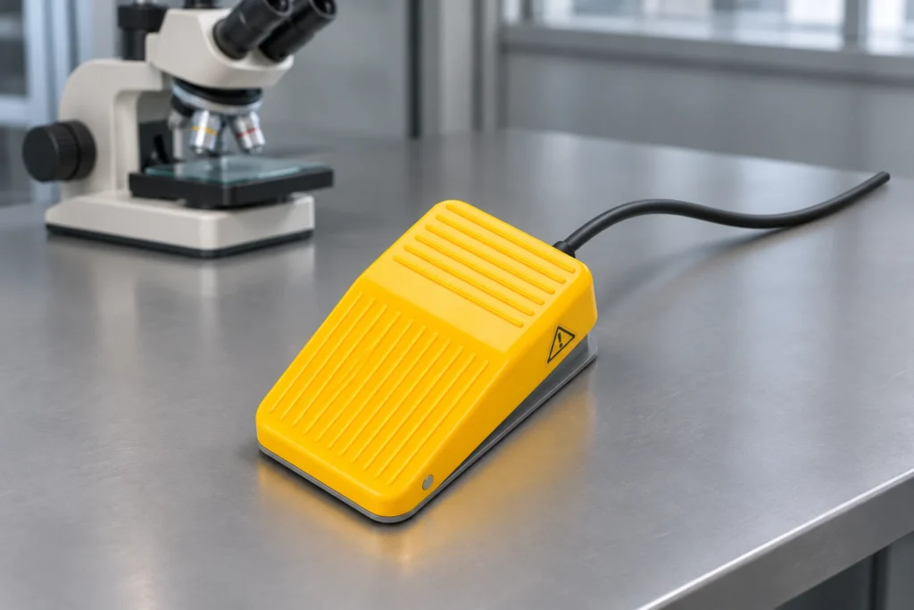
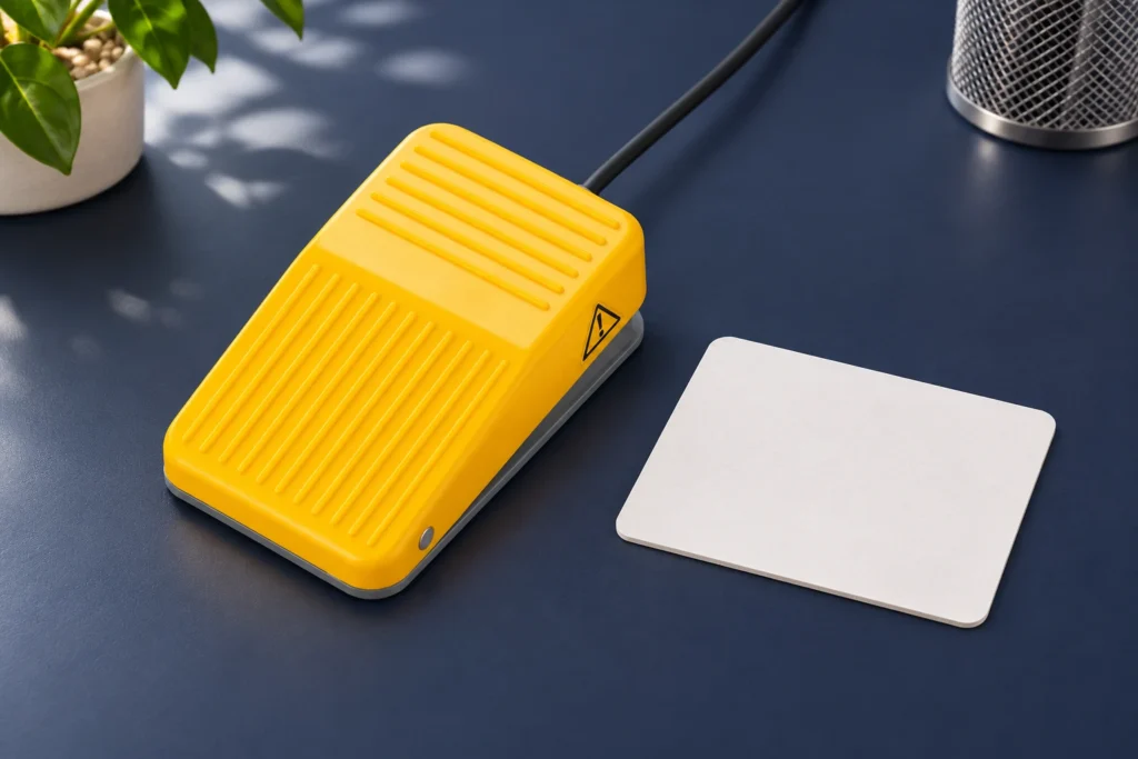
Foot switch cable jacket thickness evidence should identify the supplied cable, distinguish the outer sheath from the insulation around each conductor, and report measurements against an applicable cable specification. An outside diameter reading alone does not establish sheath wall thickness. Ask for a traceable sample identity, a defined preparation and measurement method, and the acceptance requirement used by the laboratory or supplier. This guide helps buyers organize that request for a foot switch assembly without inventing a minimum thickness, assuming a cable polymer, or treating a component photograph as proof of cable construction or compliance.Identify the cable before requesting a thickness reportStart with the complete foot switch order code and the approved cable description. Cable length, connector arrangement, conductor details and jacket construction can change between orders. A report for another lead may be technically sound but irrelevant to the goods being purchased. Ask the supplier to connect the report to the exact cable part number, revision and production or material lot used in your assembly.The Lemaele LF series foot switch page provides the product context and notes wiring customization. It does not establish a sheath thickness limit or identify the polymer in every supplied lead. Use that page to begin the inquiry, then confirm the ordered construction in writing. Do not infer PVC, conductor size, cable certification or a specific cross-section from a photograph of the pedal.Separate sheath thickness, insulation thickness and outside diameterThe outer jacket or sheath surrounds the cable assembly; individual conductor insulation is a separate layer where the selected cable construction includes it. A thickness report must name which layer is measured. A receiving inspector measuring the outside of the complete cable with a caliper is...

Lire la suite
Power Inlet Molding Gate Vestige Inspection: Buyer Checklist
Blogue LEMA Électrique

Power Inlet Molding Gate Vestige Inspection: Buyer Checklist

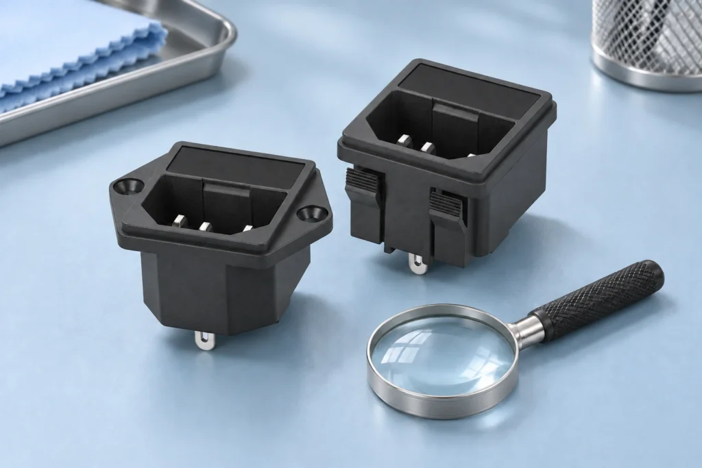
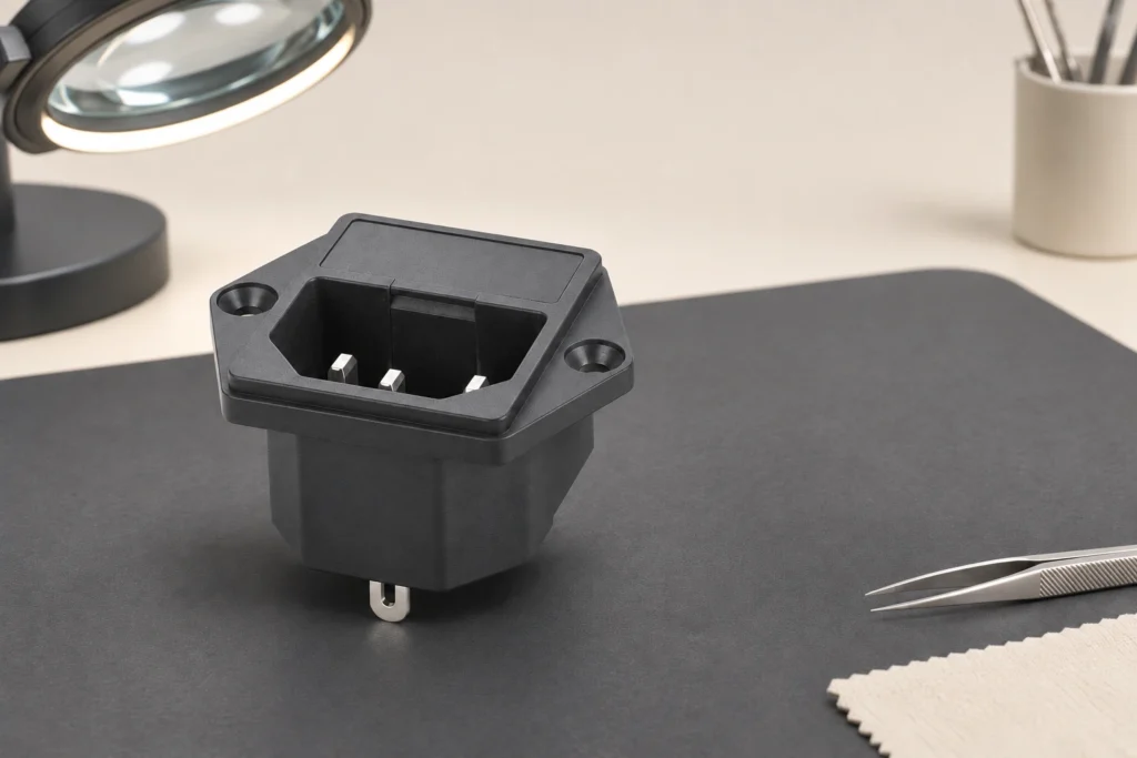
Power inlet molding gate vestige inspection should establish where a confirmed gate remnant sits, whether its height or recess meets the approved drawing, and whether it interferes with assembly. A visible mark alone does not establish a defect. Identify the molded feature with the supplier before classifying it, then compare the actual sample with location-specific acceptance criteria. For an electrical inlet, cosmetic approval also cannot replace verification of functional dimensions or electrical safety. This guide explains how buyers can request useful photographs, dimensional records and supplier decisions for the housing without guessing its resin, molding method or permitted trim dimensions.Start with the ordered housing and an approved feature mapThe question is narrower than a general molding quality audit: can the remaining material at a confirmed gate location be accepted on this ordered housing? Record the part number, mounting variant, drawing revision and sample identity first. A screw-flange housing and a snap-in housing can have different contact surfaces even when their front openings look similar. An inspection instruction transferred between them may protect the wrong area.The Lemaele IPZ series AC power socket page provides a real product reference for these discussions. Its photographs do not identify a gate position, gate type, resin grade or vestige tolerance. Ask for an annotated production drawing or a supplier-confirmed sample photograph before naming any visible mark a gate scar. Keep this confirmation in the purchasing file so later inspectors use the same location.Distinguish a gate remnant from other molded featuresA gate is an entry opening for molten polymer during molding. The IIT Bombay D’source gates lesson explains that gate choice depends on factors including the part and its appearance. This background helps explain why marks...

Lire la suite
Micro Switch Lever Edge Burrs: Define Inspection Zones and Acceptance
Blogue LEMA Électrique

Micro Switch Lever Edge Burrs: Define Inspection Zones and Acceptance

Micro switch lever edge burr inspection should identify the exact lever version, locate the questioned edge, and compare the observation with a drawing-defined acceptance requirement. A bright reflection, a rough-looking photograph, or an electrical click cannot establish whether a stamped lever edge is acceptable. Record the condition without bending or filing the lever, use a repeatable visual method, and ask the supplier for a disposition linked to the ordered assembly. This guide gives equipment buyers a practical way to distinguish an edge-condition question from operating travel, pivot clearance, and electrical performance.Start with the correct lever assemblyA micro switch family may include a basic plunger and multiple lever arrangements. The Lemaele KW7 series micro switch page describes lever options and shows more than one configuration. Before evaluating a lever edge, match the purchase order, part designation, drawing revision, actuator arrangement, and terminal version. A basic plunger sample cannot serve as the visual acceptance reference for a roller-lever assembly.Do not infer the lever alloy, thickness, heat treatment, coating, or allowable burr height from its appearance. Even when two levers look alike, their ordered configuration and contact geometry can differ. Photograph the whole switch first, then the lever and the particular edge. This establishes which component the close-up belongs to and avoids sending a supplier an isolated image with no orientation.Distinguish an unwanted projection from a specified edgeA burr is an unwanted projection at an edge; a deliberately specified chamfer, radius, or formed feature is part of the intended geometry. Removing an apparent projection does not establish that the remaining edge meets the drawing. Equally, a visibly sharp boundary is not automatically an unauthorized burr. The inspection decision needs a definition of the...

Lire la suite
Toggle Switch Bushing Roundness: Define the Surface Before Measuring
Blogue LEMA Électrique

Toggle Switch Bushing Roundness: Define the Surface Before Measuring

Toggle switch mounting bushing roundness inspection must begin with a defined surface and an agreed drawing requirement. An external thread, a smooth locating land, a panel hole, and the rotating handle are different features. A few caliper readings or a tight mounting nut cannot establish the roundness of all of them. Identify the ordered switch, specify the inspection section, and select a measurement method suited to that feature before judging the result. This guide helps buyers separate shape, size, thread fit, and mounting problems, so they request evidence that can actually resolve an assembly concern.Why the measured feature mattersA threaded mounting bushing has several surfaces with different purposes. Its thread engages mounting hardware; a shoulder or locating feature may interact with the panel; the handle passes through the upper assembly. The visible outline of the thread is not one uninterrupted smooth circle. A report that merely says bushing roundness checked leaves the reader unable to tell which of those surfaces was measured.For the Lemaele LT3230C toggle switch, use the ordered drawing and approved mounting hardware to identify the feature of interest. The product photograph establishes the family’s visible arrangement, not a geometric tolerance. Do not assign a roundness limit or select a thread gauge from an image filename, apparent scale, or a similar-looking switch.Separate roundness, diameter, and runoutDiameter describes size according to a measurement definition. Roundness evaluates the form of a circular profile. Runout involves a relationship to an axis and a rotation setup. These questions can overlap in an investigation, but their results are not interchangeable. A component can satisfy selected size readings while still needing a more complete form assessment, and a runout reading can include effects that...

Lire la suite
Power Inlet Housing Weld Lines: Inspect Appearance and Request Evidence
Blogue LEMA Électrique

Power Inlet Housing Weld Lines: Inspect Appearance and Request Evidence

Power inlet housing weld line inspection begins by locating a suspected molding line, recording its position, and checking it against an agreed drawing and appearance reference. A photograph alone cannot establish strength, insulation performance, or acceptance. Separate a surface observation from a functional concern, preserve the original sample, and ask the supplier to connect any evaluation to the exact ordered inlet. For equipment buyers, this prevents two expensive errors: rejecting an acceptable cosmetic feature without a requirement, or accepting a critical housing concern because the inlet still fits the panel. The following workflow explains what to record and when to escalate.What a suspected weld line actually tells youA weld line is associated with the meeting of polymer flow fronts during molding. Its position can be influenced by features that split the flow. However, a narrow mark on a finished housing is not automatically a confirmed weld line. A parting line, scratch, surface contamination, and a crack can look similar in an isolated close-up. Record the feature as a suspected line until the manufacturer has reviewed its location and manufacturing context.Research by Saito and colleagues, published through the Japan Society of Polymer Processing, examines flow and temperature around an obstructive pin. The published study abstract supports the general connection between flow history and line formation. It does not characterize an IPZ housing or provide a pass limit for your inlet. Keep that distinction in the inspection report.Identify the inlet and the observation zoneStart with the purchase order, supplier part designation, drawing revision, and delivery lot. The Lemaele IPZ series AC power socket page identifies the relevant product family. Its product illustration includes different mounting arrangements. Choose the exact ordered arrangement before...

Lire la suite
Limit Switch Housing Coating Adhesion: Specify Useful Inspection Evidence
Blogue LEMA Électrique

Limit Switch Housing Coating Adhesion: Specify Useful Inspection Evidence

Limit switch housing coating adhesion evidence should identify the actual substrate, coating system, test specimen and method before a buyer accepts a result. A good-looking finish does not prove attachment, and a tape-test rating does not establish corrosion life or enclosure sealing. For an LZ1 series inquiry, confirm the selected housing finish and the requirement that the evidence must answer. This guide helps OEM buyers request interpretable coating records without damaging installed equipment or borrowing unrelated acceptance limits. It establishes no Lemaele coating chemistry, mandatory adhesion class, test approval or environmental performance claim.Confirm which housing and finish the report coversUse the LZ1 series limit switch product page to identify the relevant product family, then confirm the ordered version and drawing with the supplier. A blue housing in a photograph does not identify the coating chemistry, preparation process or layer structure. Request the controlled finish description for the actual order before choosing a test method.Identify the surface of interest. The main enclosure, removable cover, mounting ears, screws and actuator assembly may not share one finish or substrate. A result from one of those surfaces should not be relabelled as a result for every exposed part. Mark the location on a drawing or photograph and retain the connection between that location and the reported specimen.The heavy-duty limit switch selection guide covers the broader sourcing decision. Keep actuator arrangement, electrical configuration, mounting and operating environment in the specification. Coating attachment is a useful quality question within that decision. It cannot replace evidence that the selected switch version meets the functional and installation requirements of the machine.Separate visible condition from adhesion evidenceInspect and photograph the as-received finish before any destructive work. Record chips, scratches,...

Lire la suite
Foot Switch Cable Jacket Durometer: Read Hardness Reports Correctly
Blogue LEMA Électrique

Foot Switch Cable Jacket Durometer: Read Hardness Reports Correctly

Foot switch cable jacket durometer evidence is useful only when the report identifies the material, specimen, hardness scale and measurement conditions. A bare number does not prove that a cable is flexible enough for repeated pedal movement or suitable for a particular machine. For an LF series inquiry, first confirm the ordered cable construction and ask how the tested specimen represents it. This guide explains how OEM buyers can review hardness information without mistaking a material result for complete cable qualification. It provides no assumed LF jacket polymer, Shore target, approved test setup or service-life prediction.Start with the cable actually being purchasedThe LF series foot switch product page is the product reference for this inquiry. Confirm whether the requested order includes a cable, its controlled construction identifier and the applicable drawing revision. A catalogue photograph cannot identify the polymer formulation or prove that every offered wiring configuration uses the same jacket. Obtain the information for the version being quoted.Explain why you need hardness information. You may be comparing approved incoming material, investigating a noticeably changed jacket feel or documenting a specified cable construction. Those questions require traceable comparisons. They do not justify choosing an arbitrary hardness target and asking the supplier to match it. Start with the application requirement and the evidence already available for the selected construction.The electric foot switch selection guide places the cable question within the wider control selection. Keep the pedal, contacts, enclosure, connection and machine application in scope. A good material report cannot compensate for an unsuitable electrical configuration or installation. Record who owns cable approval and who approves the complete control for the equipment.Read the scale with the numberDurometer hardness describes resistance to a...

Lire la suite