
IEC power inlet creepage and clearance must be assessed in the finished assembly as well as within the component. Clearance is the shortest relevant path through air; creepage follows the relevant insulating surface. Panel screws, wire routing and nearby conductive parts can change the assembly paths. There is no universal spacing that can be selected from mains voltage alone.
O Tomada de Corrente CA da Série IPZ is the LEMA product reference illustrated here. Its photograph identifies the external product, not an unlisted rating, accessory compatibility or test result. Obtain the current specification for the full order code before approving an assembly.
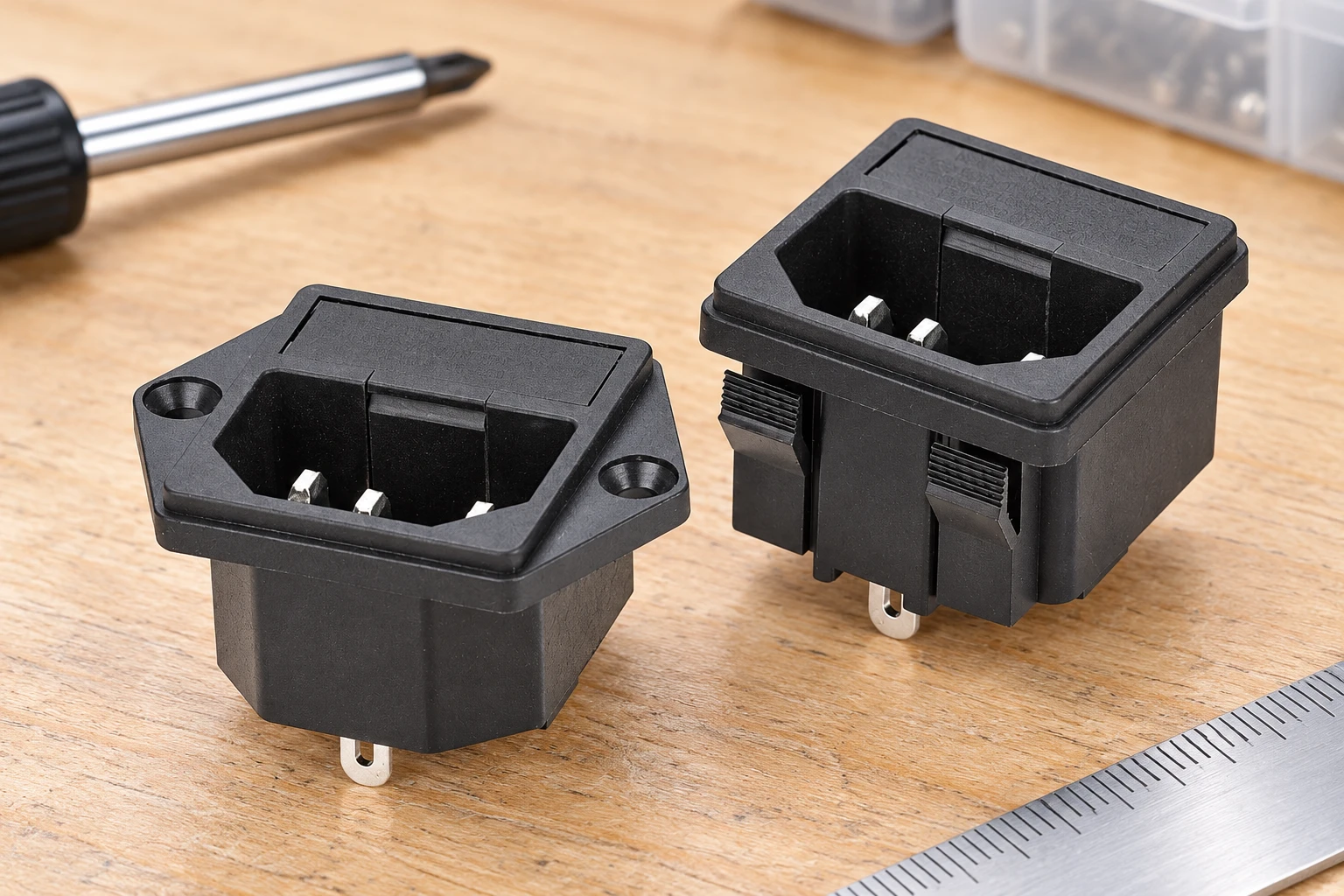
Begin with the electrical design of the completed equipment. Identify the conductive parts at each side of the relevant boundary and the function that the insulation provides. The inlet terminals, enclosure, mounting hardware, adjacent components and connected wiring may all be relevant. Measuring the most visible gap without defining the boundary can produce a precise number for the wrong question.
Keep the component boundary distinct from the equipment boundary. An inlet can have documented construction and approval conditions while the finished installation still introduces another path through a nearby screw, bracket or wire. Obtain the current inlet drawing and the conditions applicable to the exact variant, then review how it is installed in the actual enclosure.
Distinguish a path through air from one along a surface
Clearance concerns the relevant shortest path through air between conductive parts. Creepage concerns the relevant shortest path along an insulating surface. These measurements can follow different routes around the same pair of parts. A large visible space in front of a component does not establish the shortest path behind it or along its supporting material.
Ribs, grooves, joints and changes of material can affect how a path is evaluated under the applicable method. Do not assume that an added slot or a raised feature automatically provides the required benefit. The geometry needs to meet the relevant interpretation rules. Document the route being assessed and the rule used, especially where the path crosses a material interface or an assembly joint.
Obtain the requirement from the applicable equipment assessment
The required spacing is not a universal value selected from the nominal supply voltage. The responsible assessment must consider the applicable equipment standard and insulation function, together with the electrical and environmental conditions relevant to that standard. Working voltage, transient conditions, pollution, material characteristics and altitude can enter the assessment in different ways.
Keep the design inputs and their documentary basis visible. A material colour or the appearance of a molded housing does not establish its tracking classification. An installation described as indoor is not enough to determine every pollution condition. Obtain the relevant material and application information instead of assigning a favourable classification because it produces a convenient distance.
Use the current applicable requirements for the product and market. A general tutorial can explain the concepts, but an old example may cite an edition or equipment category that does not govern the present design. Record the standard, edition and accepted assessment basis with the design review. A catalogue description establishes scope, not the complete measurement or acceptance method.
Review the rear termination region
Rear terminations can be closer to enclosure features than the front mating chamber suggests. Examine the complete installed terminal, its mating connection, insulation system and wire routing. Include nearby screws, brackets and conductive shields in the review. A photograph of a bare inlet does not represent the geometry after the harness and surrounding components have been installed.
Check the permitted movement of flexible conductors and connectors. A carefully arranged prototype may show a larger gap than the assembly retains during handling or service. Define support and routing so that the relevant minimum condition is controlled. Do not rely solely on an operator pushing a wire away from a metal part before the cover closes.
Review loose strands, preparation length and displaced insulating sleeves where these are relevant to the approved termination system. The purpose is to preserve the accepted construction, not to recommend a generic wiring method. The equipment and connector instructions determine the permitted assembly. A different terminal or mating connector can require another spacing assessment even when the front inlet form remains unchanged.
Include the panel, fasteners and neighbouring parts
Mounting hardware can introduce a conductive feature into a previously clear region. Review the specified screw length, washers, retaining features and the range of permitted installation positions. A screw that does not interfere mechanically can still matter to an insulation path. Keep the hardware definition on the approved assembly drawing rather than leaving it to an unspecified workshop choice.
The finished panel condition also matters to the physical installation. Distortion, incomplete seating or a changed retention method can reposition the inlet relative to the enclosure. Dimensional fit and insulation spacing are separate checks that should share the same accepted configuration. Do not approve a spacing drawing for one flange arrangement and then install a different mounting variant without review.
Organize an assembly-level spacing review
| Rever item | Evidence to obtain | Reason for further assessment |
|---|---|---|
| Electrical boundary | Defined conductive parts and insulation function | The measured gap does not match the required boundary |
| Air path | Shortest relevant route in the installed geometry | Nearby wire or hardware changes the minimum |
| Surface path | Insulating route and applicable measurement rules | Unverified assumptions about a rib, groove or joint |
| Requirement inputs | Equipment standard, environment and material evidence | A universal number is substituted for the assessment |
| Assembly control | Specified inlet, terminations, routing and hardware | The production configuration differs from the drawing |
| Verificação | Measured observations and required electrical tests | A drawing or withstand result is treated as complete proof |
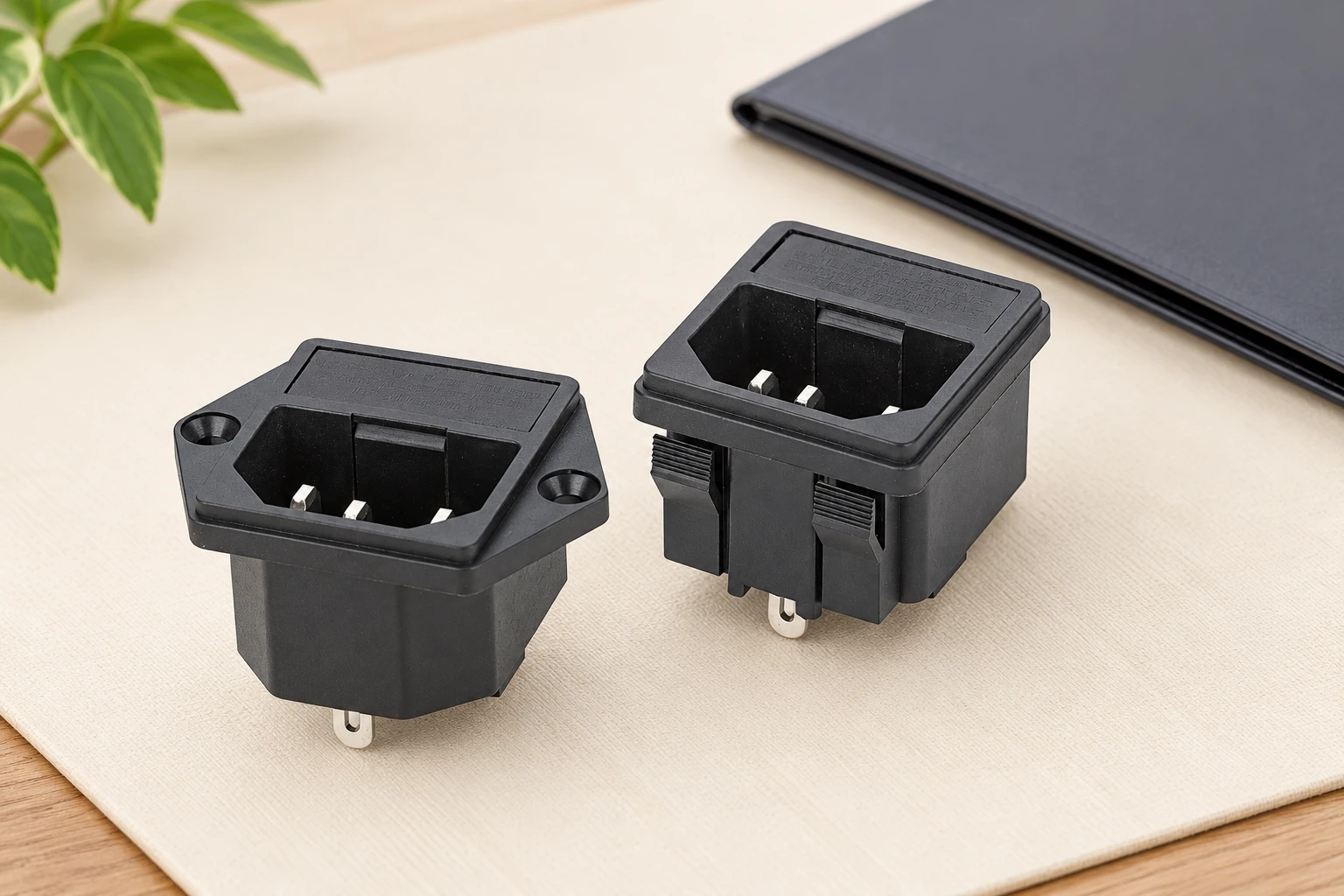
This is a qualitative review framework. It intentionally supplies no minimum distance, voltage category or material classification for a LEMA product. The appropriate values and methods must come from the exact component documentation and applicable equipment requirements.
Measure representative geometry with an appropriate method
Plan the measurement around the shortest relevant route and the physical features that define it. Identify the drawing revision, sample condition, instrument and method. A simple straight measurement may be useful for an unobstructed air gap but may not describe a surface route around a feature. Select a method that can resolve the actual path under the applicable assessment rules.
Account for production variation in component positions, hardware and assembly. Record the condition that the measurement represents rather than presenting a nominal design gap as an inspected minimum. Where access is difficult, preserve the evidence needed to show the assessed geometry, such as controlled drawings, suitable images and the relevant measurement record.
Keep spacing evidence separate from electrical tests
A spacing assessment examines construction and geometry. A dielectric test applies a specified electrical stress under a controlled method. They answer related questions but do not automatically replace one another. A successful test observation does not prove that every assembly variation retains the required distance, and a favourable drawing review does not mean an electrical test was executed.
Use qualified personnel and approved isolation, test and discharge arrangements where electrical testing is required. Preserve the exact configuration and acceptance record. When a repair or substitution changes the inlet, terminal arrangement, harness or mounting hardware, assess the affected paths again before release. The accepted result belongs to the documented assembly and requirements, not to the product photograph.
Review the final geometry and applicable requirement
Document the conductive features on both sides of each relevant insulation boundary, including terminals, fasteners, shields and wires. Use the actual enclosure geometry and manufacturing tolerances. A cable that can move toward a nearby part may create a different minimum path from a carefully arranged prototype. Record the basis for the required distances and material/environment classifications under the applicable current equipment standard.
Keep geometrical assessment distinct from dielectric testing. A successful withstand observation does not automatically establish every required creepage path or clearance under all assembly tolerances. Conversely, a drawing review is not an executed electrical test. The illustrated IPZ inlet is a component example, not approval of a completed enclosure. Obtain its current drawing and approval conditions and complete the equipment assessment before release.
Technical references and the scope of this review
IEC insulation coordination catalogue: The current IEC 60664-1 consolidated edition addresses insulation coordination, including clearances and creepage distances. Use its applicable requirements with the equipment standard; this catalogue summary does not supply a universal spacing.
HSE guidance for safe electrical testing: Keep the equipment isolated for inspection and apply the approved assessment procedure. A spacing review is not a substitute for the specified electrical tests.
For the wider component decision, see Tipos de Tomadas de Alimentação AC: Guia Global de Fabricação e Aprovisionamento OEM. Complementary checks are covered in IEC Power Inlet Panel Cutout and Mounting Guide e Equipment Power Inlet Replacement: Match, Inspect and Validate. These pages address separate questions and do not replace the acceptance evidence defined here.
Further learning
This independent educational lesson explains choosing the applicable insulation-spacing standard. It uses PCB examples; use the current equipment requirements for the finished inlet assembly rather than copying a spacing value or an old edition.

Watch PCB Clearance and Creepage Distances, Part 1: Which Standard Applies? — Elektor TV
Perguntas frequentes
Are creepage and clearance the same path?
No. Creepage follows the relevant insulating surface; clearance follows the relevant path through air.
Can voltage alone determine spacing?
No. Apply the relevant equipment requirements and the associated material, environment and insulation conditions.
Does a compliant inlet approve the whole enclosure?
No. Wires, screws, adjacent parts and installation geometry still need an assembly-level assessment.
Can withstand testing replace the spacing review?
No. Keep the required geometrical assessment and electrical tests as distinct acceptance evidence.