LEMA NEWS CENTER

News & Blog

News Center

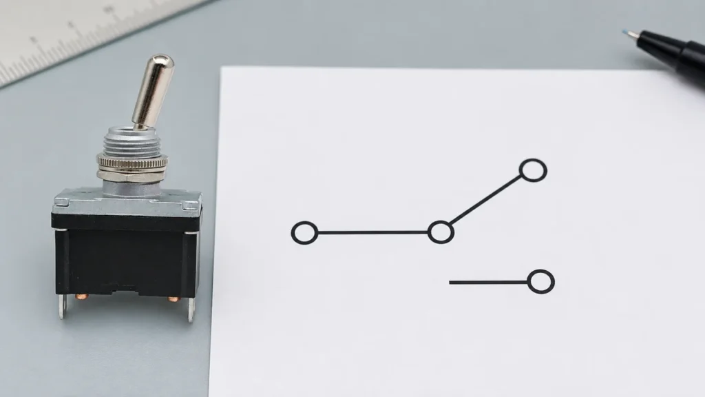
SPDT Switch Symbol, Terminal Logic and Schematic Guide
Blog LEMA Electric

Guia de Símbolos, Lógica de Terminais e Esquemáticos de Interruptores SPDT

o símbolo do comutador SPDT tornou-se uma prioridade porque a Google Search Console já mostra impressões reais para este tópico no LEMA. Esse sinal indica um público existente, mas a cobertura anterior do site não correspondia totalmente à questão. Este guia transforma a consulta num fluxo de trabalho prático de seleção, integração e compra para projetistas de equipamentos, montadores de painéis, equipas de manutenção e compradores industriais. O símbolo do comutador SPDT mostra um contacto comum móvel que pode ligar-se a qualquer um de dois contactos estacionários. Descreve a lógica elétrica, e não a vista física de um comutador real. Um esquema pode mostrar o estado normal ou desenergizado de acordo com a sua convenção de desenho, enquanto a parte traseira de um produto pode espelhar o que uma premissa de vista frontal sugere. Identifique os fios como COM, NA e NF — ou comum, via A e via B — apenas após verificar o diagrama do fabricante e a continuidade. O SPDT pode selecionar sinais, inverter a lógica, fornecer saídas alternadas ou criar um par NA/NF para uma entrada de controlador. Vista de aplicação que mostra os pontos de integração práticos para o símbolo do comutador SPDT. O que o símbolo do comutador SPDT significa num projeto real Uma especificação útil começa pelo comportamento, e não por uma fotografia de catálogo. Anote o que se move, o que o operador ou a máquina estão a tentar alcançar, quando o estado elétrico deve mudar e o que deve acontecer se um condutor abrir ou o dispositivo não reiniciar. Separe o dispositivo de campo da lógica do controlador: um comutador reporta ou comanda um estado, enquanto o relé, o PLC ou o circuito de controlo decide como a máquina responde. Famílias de produtos semelhantes contêm frequentemente várias disposições de contactos, estilos de atuadores, formas de terminais e versões de montagem. O nome da família ajuda à descoberta, mas não define uma peça de produção. Utilize o sufixo de modelo completo, o desenho com controlo de revisão e o diagrama de terminais...

Ler mais
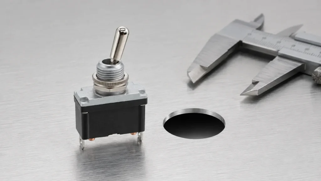
Toggle Switch Hole Size and Panel Mounting Guide
Blog LEMA Electric

Guia de Tamanho de Furo e Montagem em Painel para Interruptor de Alavanca

o tamanho do furo do comutador de alavanca tornou-se uma prioridade porque o Google Search Console já mostra impressões reais para este tópico no LEMA. Esse sinal indica um público existente, mas a cobertura anterior do site não correspondia totalmente à questão. Este guia transforma a consulta num fluxo de trabalho prático de seleção, integração e compra para projetistas de equipamentos, montadores de painéis, equipas de manutenção e compradores industriais. O tamanho do furo do comutador de alavanca não é um número universal. A abertura necessária depende do diâmetro da bucha ou do corpo de encaixe rápido, do elemento antirrotação, da espessura do painel, do conjunto de anilhas e da tolerância permitida do modelo exato. Uma designação de rosca nominal não é uma instrução de corte final. Utilize o desenho do fornecedor, meça amostras aprovadas e faça uma peça de teste no material real do painel e no revestimento. Verifique a folga traseira para os terminais e cablagem, a folga da alavanca em todas as posições e o acesso da ferramenta para a porca de montagem. Para modelos estanques, a extremidade do furo e a compressão da junta fazem parte da via de infiltração. Vista de aplicação que mostra os pontos de integração práticos para o tamanho do furo do comutador de alavanca. O que significa o tamanho do furo do comutador de alavanca num projeto real Uma especificação útil começa pelo comportamento, não por uma fotografia de catálogo. Anote o que se move, o que o operador ou a máquina está a tentar alcançar, quando o estado elétrico deve mudar e o que deve acontecer se um condutor abrir ou se o dispositivo não reiniciar. Separe o dispositivo de campo da lógica do controlador: um comutador relata ou comanda um estado, enquanto o relé, o PLC ou o circuito de controlo decide como a máquina responde. Famílias de produtos semelhantes contêm frequentemente várias disposições de contactos, estilos de atuadores, formas de terminais e versões de montagem. O nome da família ajuda na descoberta, mas não define uma peça de produção. Utilize o sufixo completo do modelo, com controlo de revisão...

Ler mais
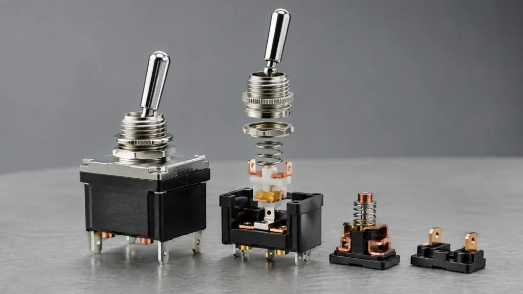
Toggle Switch Mechanism: How It Works and How to Select One
Blog LEMA Electric

Mecanismo do Interruptor de Alavanca: Como Funciona e Como Selecionar um

o mecanismo de comutador de patilha tornou-se uma prioridade porque a Google Search Console já mostra impressões reais para este tópico no LEMA. Esse sinal indica um público existente, mas a cobertura do site anterior não correspondia totalmente à questão. Este guia transforma a consulta num fluxo de trabalho prático de seleção, integração e compra para projetistas de equipamentos, montadores de painéis, equipas de manutenção e compradores industriais. Um mecanismo de comutador de patilha utiliza a alavanca para mover ou encaixar contactos internos entre posições estáveis ou de retorno por mola. A contagem de polos indica quantos circuitos separados são controlados; a contagem de vias indica quantos caminhos cada polo pode selecionar. As legendas ON-OFF, ON-ON e ON-OFF-ON descrevem as posições estáveis, enquanto os parênteses ou uma notação específica da folha de dados podem indicar posições momentâneas. A ação de disparo (snap action) pode produzir uma transição elétrica rápida, mesmo quando o operador move a alavanca lentamente. A seleção deve associar a função de contacto à geometria real do painel, à carga, à vedação ambiental e à interface humana. Vista de aplicação que mostra os pontos de integração práticos para o mecanismo de comutador de patilha. O que o mecanismo de comutador de patilha significa num projeto real Uma especificação útil começa pelo comportamento e não por uma fotografia de catálogo. Anote o que se move, o que o operador ou a máquina está a tentar alcançar, quando o estado elétrico deve mudar e o que deve acontecer se um condutor abrir ou o dispositivo falhar a reposição. Separe o dispositivo de campo da lógica do controlador: um interruptor relata ou comanda um estado, enquanto o relé, o PLC ou o circuito de controlo decide como a máquina responde. Famílias de produtos semelhantes contêm frequentemente várias disposições de contactos, estilos de atuadores, formas de terminais e versões de montagem. O nome da família ajuda à descoberta, mas não define uma peça de produção. Utilize o sufixo do modelo completo, o desenho controlado por revisão e o diagrama de terminais. Se alguma seleção...

Ler mais
Metal Push Button Switch: Durability, Panel Mounting and Selection Guide
Blog LEMA Electric

Interruptor de Pressão Metálico: Durabilidade, Montagem em Painel e Guia de Seleção

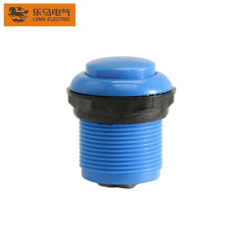
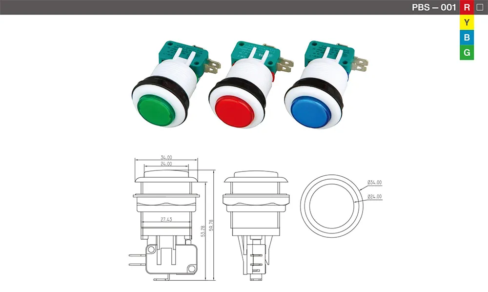
A metal push button switch puts a harder bezel and actuator on the panel face, but front-panel durability still depends on material grade, gasket torque, impact test scope, and whether the switch behind the head can survive over-travel. This guide contrasts metal and plastic bezels, separates anti-vandal marketing from IK proof, maps abuse paths that bypass a metal face, and shows what to freeze on drawings and samples before colour or LED options enter the RFQ. Product-focused view supporting metal push button switch selection and panel integration. ContentsWhat a metal push button switch actually protects on the panelMetal bezel vs plastic heads for daily panel abuseAnti-vandal marketing vs IK and seal proof buyers should demandPanel wear: gaskets, torque, and fixing mistakes that defeat a metal headAbuse paths that bypass a metal bezelDrawing and sample proof before you trust a metal operatorSelecting PBS Series options after metal and abuse requirements are documentedFAQsWhat a metal push button switch actually protects on the panel A metal push button switch is not a single material specification. In procurement language it usually means the visible bezel and actuator are metal—often a stainless steel push button or nickel-plated brass in public-facing designs—so finger impact, key scratches, and daily panel wear hit a harder surface than a light-duty plastic panel switch head. That front hardness is real, but it is bounded. The Bezel / actuator pair can still dent, spin in the hole, or leak behind the panel if the gasket stack, nut torque, or rear switch path is wrong. Treat “metal” as a front-abuse decision, not proof of IK impact class, ingress sealing, or internal contact life. On a self-service kiosk, the metal ring is what...

Ler mais
Industrial Push Button Switch Selection: Environment, Duty and OEM Guide
Blog LEMA Electric

Seleção de Interruptores de Pressão Industriais: Guia de Ambiente, Serviço e OEM

An industrial push button switch matches the panel zone first: dust, moisture, temperature swings, and vibration set the sealing and mounting stress before you compare actuators on a control panel. This article walks environment classification, mechanical cycle duty, electrical contact logic, LED illumination options, colour codes, and RFQ fields that keep procurement aligned with real machine conditions. Product-focused view supporting industrial push button switch selection and panel integration. ContentsHow Dust and Moisture Change Push Button SelectionTemperature Swings and Vibration at the Panel EdgeMechanical Cycle Duty: Matching Press Frequency to Switch LifeElectrical Interface Questions Before You Lock a Part NumberColour Codes and LED Options for Operator ClarityOEM RFQ Fields That Prevent Wrong-Spec DeliveriesSelect a PBS Industrial Push Button for Your Panel JobFAQHow Dust and Moisture Change Push Button Selection Dust and moisture decide whether a panel mount push button switch survives at the cutout, not just behind the bezel. Every hole is an ingress path, and IP rating thinking should follow the wettest zone on the control panel. Community builders note that adding buttons to a certified enclosure can change how the whole door performs against dust and spray. Important: Forum makers report that splashing water can press a tact switch unintentionally — wet zones need an actuator sealing plan, not only a higher IP label on a catalog line. Panel zone signal What to document in RFQ Why it matters for selection Dry indoor cabinet Dust class, occasional wipe-down Sealing focus on bezel gap and cable entry Humid or wash-adjacent Spray direction, chemical exposure Panel hole and actuator seal become primary Mixed door (display + buttons) Which functions sit in wettest area Example industrial operator families cite IP65 for dust...

Ler mais
SPDT KW10 Limit Micro Switch: Terminals, Actuation and Selection
Blog LEMA Electric

Micro-interruptor de limite SPDT KW10: Terminais, Acionamento e Seleção

spdt kw10 limit micro switch became a priority because Google Search Console already shows real impressions for this topic on LEMA. That signal indicates an existing audience, but the previous site coverage did not fully match the question. This guide turns the query into a practical selection, integration and purchasing workflow for equipment designers, panel builders, maintenance teams and industrial buyers. A KW10-style SPDT micro switch normally exposes COM, NO and NC terminals. In the released state COM is connected to one throw; after actuation the snap mechanism transfers COM to the other. The family name does not guarantee identical terminal orientation, actuator force, life or electrical rating across suppliers and suffixes. Trace the markings on the exact component, confirm both states with an unpowered continuity test, and align the actuator so the target supplies adequate operating travel without crushing the plunger. Use the changeover contact to obtain the controller logic you need rather than assuming NO is always the preferred choice. Application view showing practical integration points for spdt kw10 limit micro switch. What spdt kw10 limit micro switch means in a real design A useful specification begins with behavior, not a catalogue photo. Write down what moves, what the operator or machine is trying to achieve, when the electrical state must change, and what should happen if a conductor opens or the device fails to reset. Separate the field device from the controller logic: a switch reports or commands a state, while the relay, PLC or control circuit decides how the machine responds. Similar product families often contain several contact arrangements, actuator styles, terminal forms and mounting versions. The family name helps discovery but does not define a...

Ler mais
Ultra Miniature Micro Switch Selection and Integration Guide
Blog LEMA Electric

Guia de Seleção e Integração de Microinterruptores Ultra Miniatura

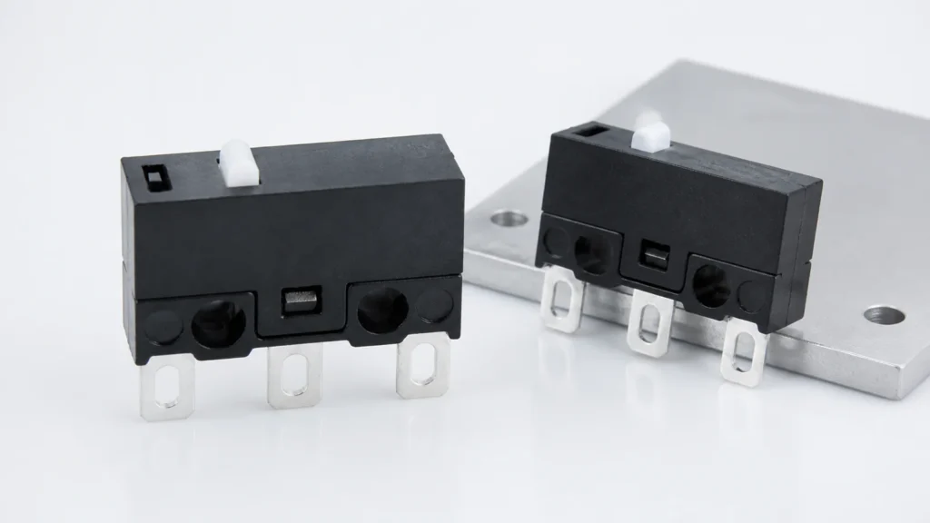
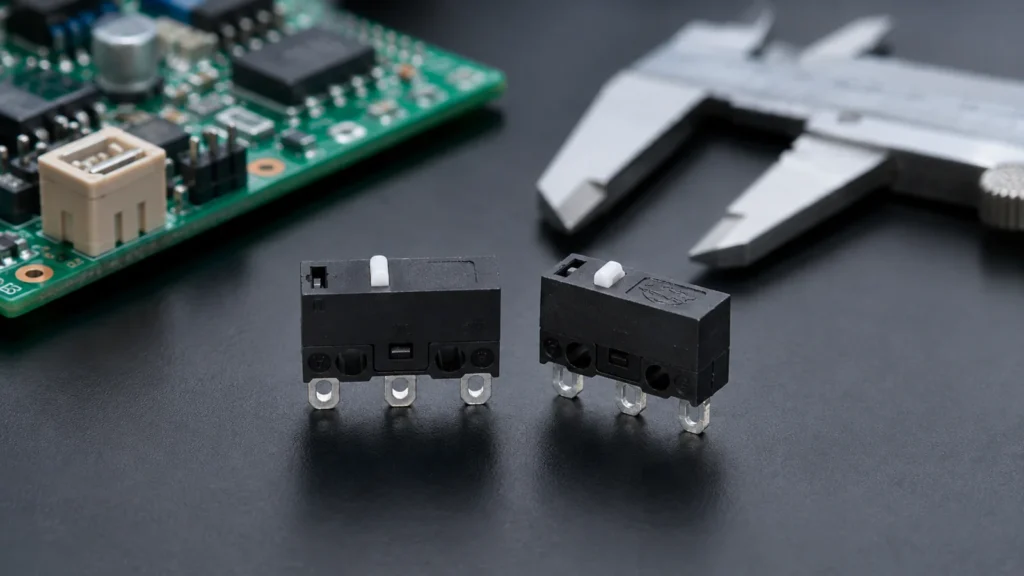
ultra miniature micro switch became a priority because Google Search Console already shows real impressions for this topic on LEMA. That signal indicates an existing audience, but the previous site coverage did not fully match the question. This guide turns the query into a practical selection, integration and purchasing workflow for equipment designers, panel builders, maintenance teams and industrial buyers. An ultra miniature micro switch saves volume only when its actuator, terminals and tolerance chain are designed together. Small housings usually leave less room for misalignment, soldering heat, board flex and excessive overtravel. Select the actuator by the motion presented by the product: a direct plunger suits controlled linear travel, while a lever can reduce operating force and absorb some approach variation. PCB models require special attention to hole pattern, seating, solder profile, cleaning process and mechanical support. The PCB should not become the stop that absorbs external impact. Application view showing practical integration points for ultra miniature micro switch. What ultra miniature micro switch means in a real design A useful specification begins with behavior, not a catalogue photo. Write down what moves, what the operator or machine is trying to achieve, when the electrical state must change, and what should happen if a conductor opens or the device fails to reset. Separate the field device from the controller logic: a switch reports or commands a state, while the relay, PLC or control circuit decides how the machine responds. Similar product families often contain several contact arrangements, actuator styles, terminal forms and mounting versions. The family name helps discovery but does not define a production part. Use the complete model suffix, revision-controlled drawing and terminal diagram. If any selection...

Ler mais
Push Button Colour Standards for Industrial Control Panels
Blog LEMA Electric

Normas de Cores de Botões de Pressão para Painéis de Controlo Industriais

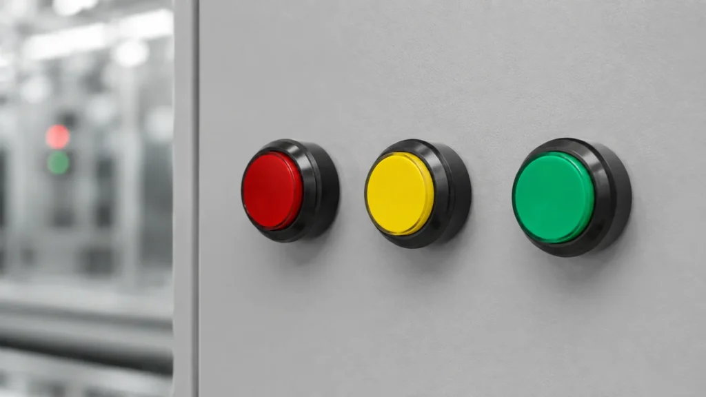
push button colour standards became a priority because Google Search Console already shows real impressions for this topic on LEMA. That signal indicates an existing audience, but the previous site coverage did not fully match the question. This guide turns the query into a practical selection, integration and purchasing workflow for equipment designers, panel builders, maintenance teams and industrial buyers. Push-button colour communicates expected action, but colour alone must never carry the entire meaning. A control panel should combine colour with a durable text label, symbol, position and consistent operating sequence. Red is commonly reserved for emergency or stop-related functions, green is commonly associated with starting or a normal condition, and yellow often signals an abnormal condition or intervention. The exact assignment depends on the applicable machine and market standards. Designers should document the selected convention, review local requirements, and prevent illuminated buttons from creating contradictory messages when lit and unlit. Application view showing practical integration points for push button colour standards. What push button colour standards means in a real design A useful specification begins with behavior, not a catalogue photo. Write down what moves, what the operator or machine is trying to achieve, when the electrical state must change, and what should happen if a conductor opens or the device fails to reset. Separate the field device from the controller logic: a switch reports or commands a state, while the relay, PLC or control circuit decides how the machine responds. Similar product families often contain several contact arrangements, actuator styles, terminal forms and mounting versions. The family name helps discovery but does not define a production part. Use the complete model suffix, revision-controlled drawing and terminal diagram. If...

Ler mais
Cam Limit Switch Working Principle, Setup and Selection Guide
Blog LEMA Electric

Princípio de Funcionamento, Configuração e Guia de Seleção de Fim de Curso de Cames

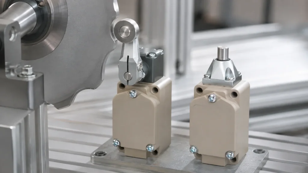
cam limit switch working principle became a priority because Google Search Console already shows real impressions for this topic on LEMA. That signal indicates an existing audience, but the previous site coverage did not fully match the question. This guide turns the query into a practical selection, integration and purchasing workflow for equipment designers, panel builders, maintenance teams and industrial buyers. A cam limit switch converts the angular position of a shaft or machine cycle into one or more electrical state changes. A rotating cam profile reaches an actuator at a chosen angle; the internal snap-action contact then changes state. The useful result is not simply “the cam touched the switch.” It is a repeatable switching window with adequate approach, overtravel and release margin. Setup therefore begins with the machine sequence: identify the earliest and latest acceptable switching angles, account for backlash and stopping distance, and make adjustments at reduced speed. Never use the switch body as the mechanical end stop. Application view showing practical integration points for cam limit switch working principle. What cam limit switch working principle means in a real design A useful specification begins with behavior, not a catalogue photo. Write down what moves, what the operator or machine is trying to achieve, when the electrical state must change, and what should happen if a conductor opens or the device fails to reset. Separate the field device from the controller logic: a switch reports or commands a state, while the relay, PLC or control circuit decides how the machine responds. Similar product families often contain several contact arrangements, actuator styles, terminal forms and mounting versions. The family name helps discovery but does not define a production...

Ler mais
Electric Foot Switch Selection Guide for Industrial Equipment
Blog LEMA Electric

Guia de Seleção de Interruptores de Pedal Elétricos para Equipamento Industrial

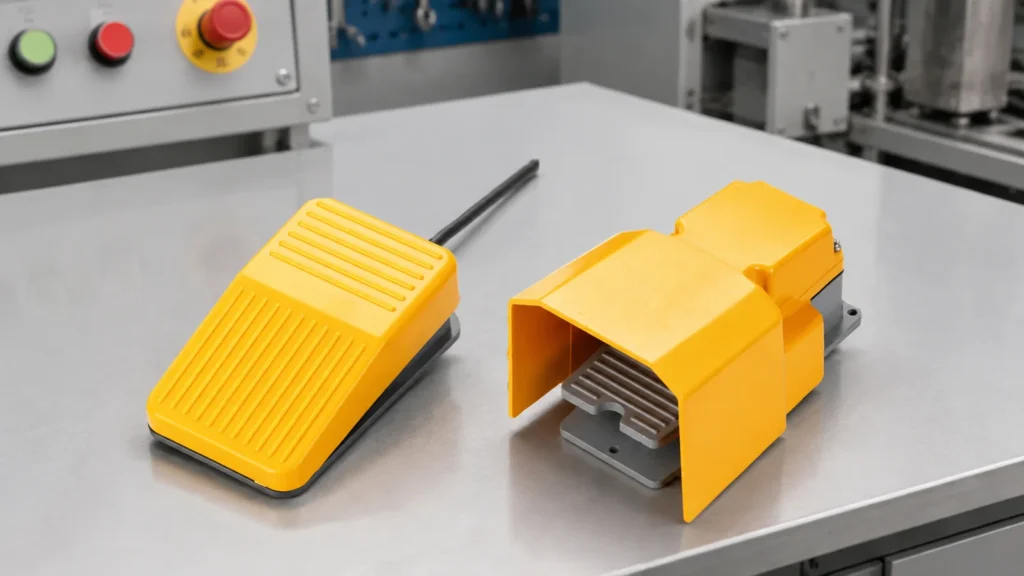
electric foot switch became a priority because Google Search Console already shows real impressions for this topic on LEMA. That signal indicates an existing audience, but the previous site coverage did not fully match the question. This guide turns the query into a practical selection, integration and purchasing workflow for equipment designers, panel builders, maintenance teams and industrial buyers. An electric foot switch gives an operator hands-free control, but it is not automatically a safeguarding device. Start by deciding whether the pedal sends a momentary start signal, maintains a circuit, jogs motion, or enables another control. Then document the normal and actuated contact states. A protected hood can reduce unintended access, while pedal shape, force, travel and floor stability determine whether the operator can use it repeatedly without awkward posture. For punching and similar machinery, the pedal must be evaluated as part of the complete control and guarding system. Do not rely on a foot control to keep hands away from a hazardous point of operation. Application view showing practical integration points for electric foot switch. What electric foot switch means in a real design A useful specification begins with behavior, not a catalogue photo. Write down what moves, what the operator or machine is trying to achieve, when the electrical state must change, and what should happen if a conductor opens or the device fails to reset. Separate the field device from the controller logic: a switch reports or commands a state, while the relay, PLC or control circuit decides how the machine responds. Similar product families often contain several contact arrangements, actuator styles, terminal forms and mounting versions. The family name helps discovery but does not define a...

Ler mais
12-Volt Power Socket Selection, Wiring and Protection Guide
Blog LEMA Electric

Guia de Seleção, Cablagem e Proteção de Tomadas de Alimentação de 12 Volts

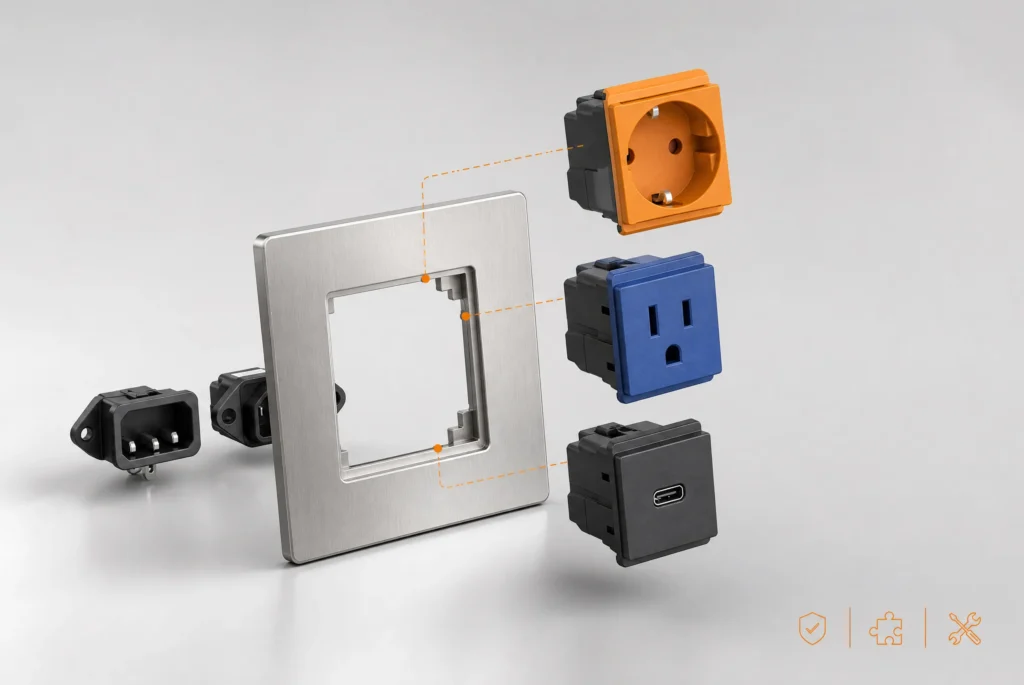
12 volt power socket selection starts by defining the required machine or equipment function, then matching the electrical interface, mechanical mounting and environment to one exact component. This guide explains matching connector format, current demand, conductors, polarity, overcurrent protection, panel mounting and environmental exposure. “12 volt” is a nominal system label rather than a complete rating. Actual voltage range, current, duty cycle, polarity, connector geometry, conductor size and protective device coordination must be defined separately. Treat every terminal diagram, rating and dimension as model-specific, and validate the assembled system before production use. What the term means in an equipment design“12 volt” is a nominal system label rather than a complete rating. Actual voltage range, current, duty cycle, polarity, connector geometry, conductor size and protective device coordination must be defined separately. This distinction matters because search results often mix replacement parts, hobby wiring examples, complete control assemblies and bare industrial components. An OEM design needs a controlled specification rather than a visual match. Record the intended function in plain language, the normal and actuated states, the equipment supply, the connected load or controller input, and the consequence of a disconnected wire.The component should be considered together with its mating part, mounting structure, conductors, enclosure and controller logic. A correct component installed in an unsuitable cutout or connected to an incompatible load is still an incorrect system. When a seller offers several variants under one family name, request the variant drawing and do not transfer ratings or terminal positions from a neighboring model. Panel power socket used to review terminals and mounting. Verify the exact model drawing before production use. Selection decisions that prevent redesignDesign inputSelection questionVerificationNominal systemWhat voltage range exists during...

Ler mais
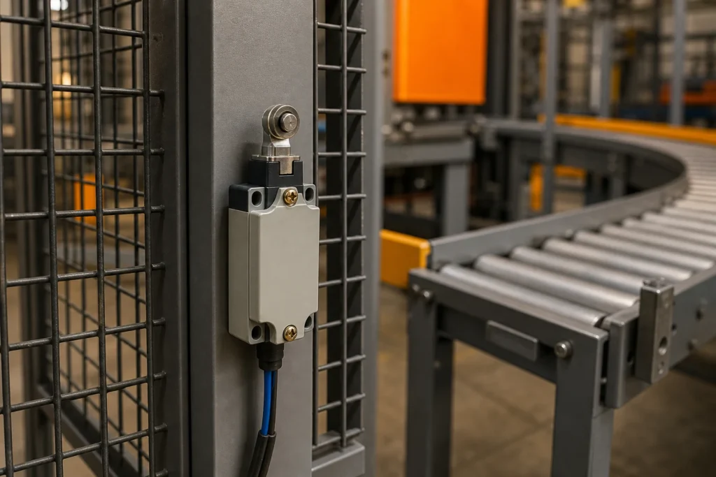
Limit Switch Accessories Selection and Integration Guide
Blog LEMA Electric

Guia de Seleção e Integração de Acessórios para Fim de Curso

limit switch accessories selection starts by defining the required machine or equipment function, then matching the electrical interface, mechanical mounting and environment to one exact component. This guide explains selecting levers, rollers, rods, brackets, glands, connectors and target cams while preserving mechanical and electrical compatibility. An accessory is part of the sensing system, not a cosmetic add-on. A lever length, roller diameter, bracket stiffness or cable gland can change operating force, travel, sealing, repeatability and service access. Treat every terminal diagram, rating and dimension as model-specific, and validate the assembled system before production use. What the term means in an equipment designAn accessory is part of the sensing system, not a cosmetic add-on. A lever length, roller diameter, bracket stiffness or cable gland can change operating force, travel, sealing, repeatability and service access. This distinction matters because search results often mix replacement parts, hobby wiring examples, complete control assemblies and bare industrial components. An OEM design needs a controlled specification rather than a visual match. Record the intended function in plain language, the normal and actuated states, the equipment supply, the connected load or controller input, and the consequence of a disconnected wire.The component should be considered together with its mating part, mounting structure, conductors, enclosure and controller logic. A correct component installed in an unsuitable cutout or connected to an incompatible load is still an incorrect system. When a seller offers several variants under one family name, request the variant drawing and do not transfer ratings or terminal positions from a neighboring model. Industrial limit switch and actuator hardware for accessory planning. Verify the exact model drawing before production use. Selection decisions that prevent redesignAccessory groupPurposeCompatibility checkActuator head or...

Ler mais