
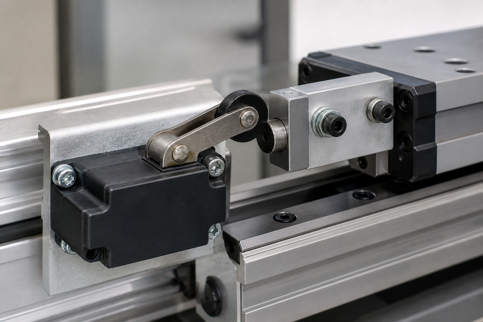
A CNC limit switch is a position-sensing device used to tell the controller that an axis has reached a defined reference or travel boundary. A reliable installation is not simply a switch placed near the end of a rail: the sensor type, contact logic, mounting rigidity, actuator geometry, cable routing, controller input, and stopping distance must work as one system. For most industrial builds, mechanical roller-lever or plunger switches remain practical choices when they are protected from chips and coolant and are actuated by a repeatable cam. The final circuit and safety functions must always be validated against the machine builder’s risk assessment, controller documentation, and applicable regulations.
What a CNC limit switch actually does
The phrase “limit switch” is often used for three related but different functions. A home switch gives the controller a repeatable reference for the machine coordinate system. A travel limit signals that an axis has reached the permitted physical travel boundary. A soft limit is a software boundary calculated after a successful homing cycle. LinuxCNC documentation makes the relationship clear: homing establishes the machine origin, while soft limits are defined relative to that origin and stop commanded movement before the physical limit switches.
One physical switch can sometimes serve as both home and limit input, but that is a controller-design decision rather than a universal wiring rule. The homing sequence may need to ignore or reinterpret a limit input while the axis approaches, trips, reverses, and moves to its final home position. Use the machine controller’s documented input scheme instead of copying a generic diagram.
A travel switch also should not be confused with an emergency-stop device or a complete machine safeguard. It can contribute position information to a control system, but it does not by itself guarantee that hazardous motion stops safely. OSHA’s machine-guarding guidance treats guards, safety devices, energy control, and maintenance procedures as parts of a broader protection system.
Mechanical, plunger, and non-contact sensing
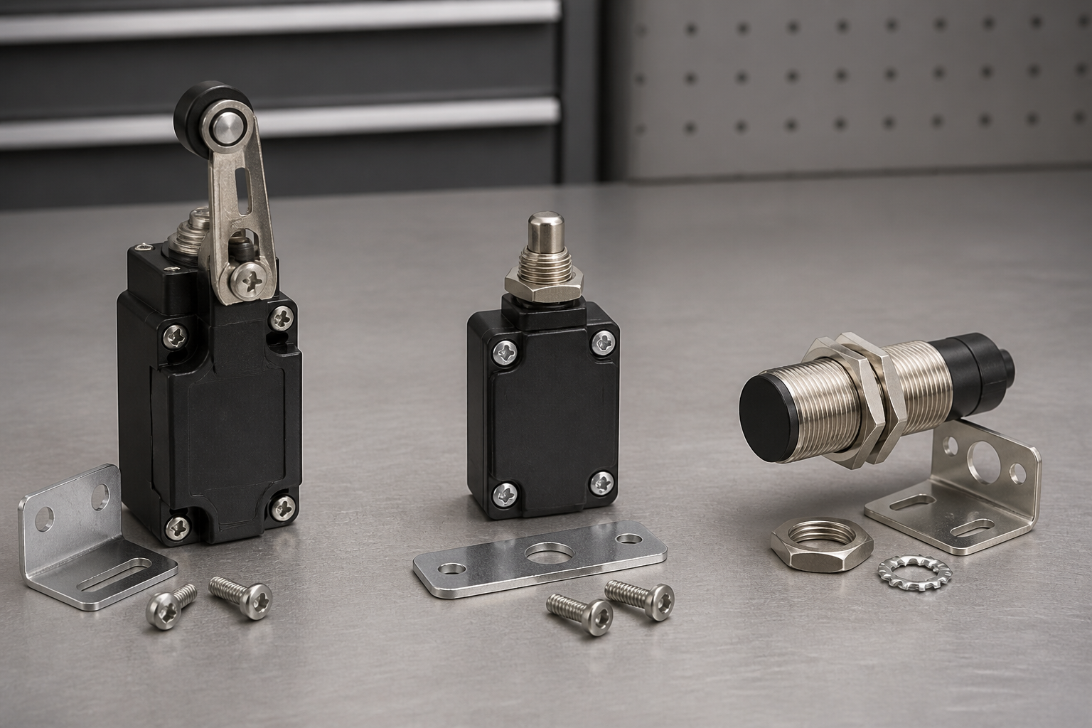
The best sensor depends on the axis environment and the accuracy required from the reference event. Mechanical switches give a positive change of contact state and are easy to diagnose. Roller levers tolerate a cam moving across the actuator, while plungers need more controlled alignment. Non-contact sensors avoid mechanical wear, but they introduce target-material, sensing-distance, supply-voltage, and controller-interface considerations.
| Sensor approach | Useful when | Main design checks | Common mistake |
|---|---|---|---|
| Roller-lever mechanical switch | A cam passes across the sensor and some alignment tolerance is needed | Approach direction, lever overtravel, return clearance, bracket stiffness, chip protection | Driving the lever into a hard stop or contacting it from the wrong direction |
| Plunger mechanical switch | There is a controlled straight-line target and compact mounting space | Target flatness, axial alignment, permitted overtravel, impact speed | Allowing side load or an angled target to scrape the plunger |
| Non-contact proximity sensor | Mechanical contact or wear is undesirable | Target material, sensing distance, supply and output type, shielding, controller compatibility | Assuming every metal target or controller input behaves the same way |
The table is a qualitative selection guide, not a substitute for a component datasheet. For mechanical options, review LEMA’s industrial limit switch product family, then compare the actuator and enclosure with the real machine geometry. The related guides to roller limit switch applications and plunger limit switch selection explain those actuator styles in more detail.
Choose the contact arrangement from the fault strategy
Mechanical limit switches commonly provide changeover contacts, allowing a designer to use a normally open or normally closed signal path. The labels describe contact state when the actuator is not operated; they do not decide which arrangement is safest for every machine.
A normally closed input is often considered when a broken conductor or disconnected plug should look like a fault, but the result depends on the controller input circuit, diagnostics, and safety architecture. A normally open input may simplify some conventional control arrangements. Neither option is automatically “fail-safe.” Document the expected input state for normal travel, switch actuation, wire break, short circuit, loss of control power, and controller restart. If the input performs a safety-related function, a qualified controls engineer must design and validate the complete safety circuit.
Position the switch before the hard stop
The trip point must leave enough distance for the axis to stop without striking the mechanical end of travel. That distance is machine-specific. It depends on speed, deceleration, drive response, load inertia, control delay, actuator movement, bracket deflection, and the distance the carriage can coast after power removal. LinuxCNC’s stepper configuration guidance likewise distinguishes the physical hard stop, the limit switch, and the soft limit, and notes that clearance is needed for an unpowered motor to coast.
Do not calculate the position from nominal switch travel alone. Start with the worst credible axis speed and load, obtain the controller and drive response data, include a margin defined by the machine risk assessment, and verify the result by controlled testing. A home switch may be located inside normal travel, while positive and negative travel limits are generally arranged near the ends. Machines with a gantry or multiple joints may require separate sensors and controller logic for alignment or squaring.
Build a repeatable actuator path
A rigid, adjustable cam is usually easier to validate than allowing an irregular carriage edge to hit the actuator. The cam should engage the roller or plunger progressively, hold the operated state across the required zone, and release cleanly when the axis reverses. Avoid sharp impact, side loading, excessive overtravel, and a geometry that can trap the lever. Lock the adjustment so vibration cannot move the trip point.
Protect the switch without hiding it
Locate the device away from direct chip streams, coolant jets, cable-chain pinch points, and maintenance foot traffic. A guard can shield the actuator while leaving enough access for inspection and replacement. Do not create a new pinch point with the guard or bracket. OSHA notes that machine guards should not create hazards and should be securely attached where possible.
Mounting and cable-routing checklist
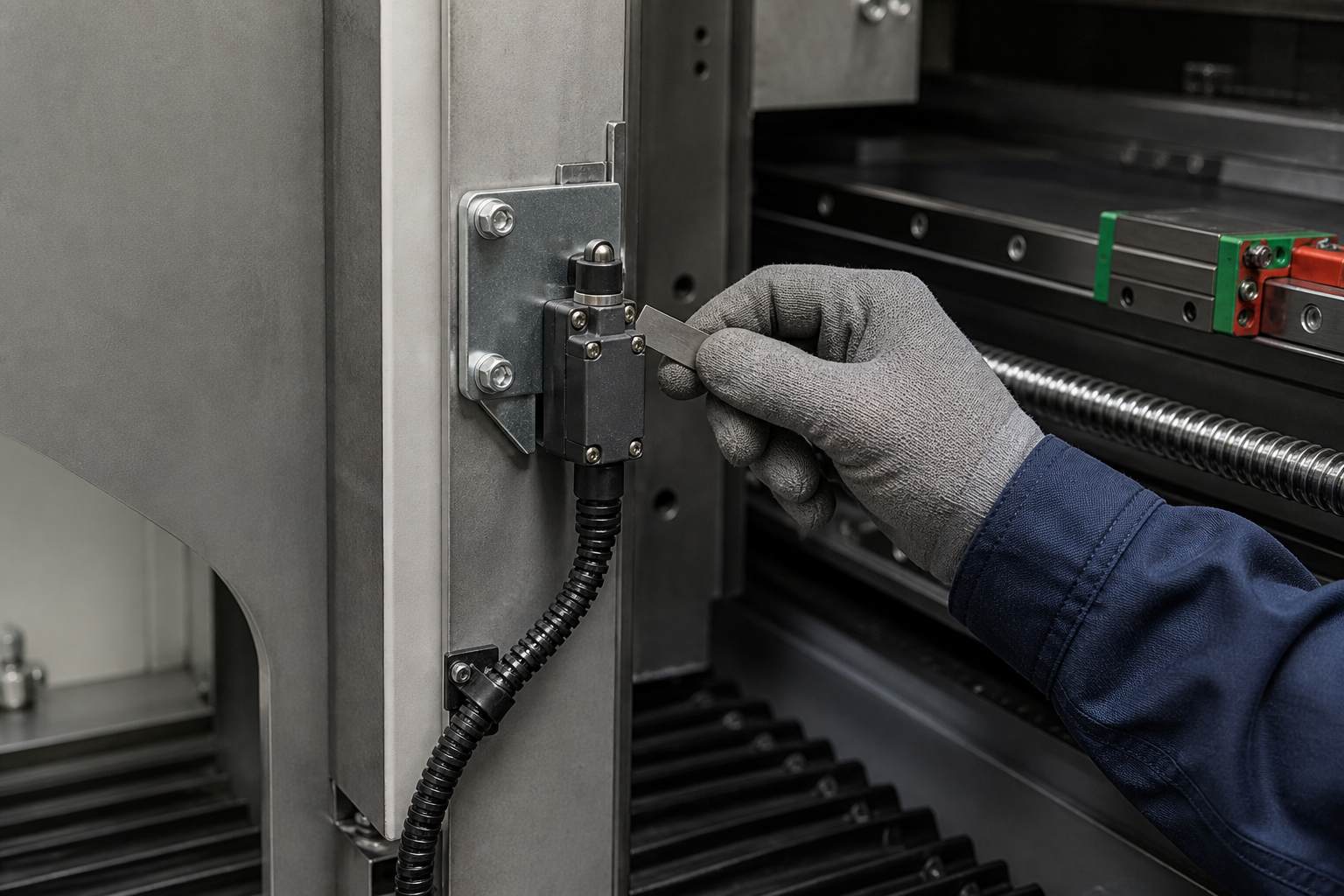
A high-quality switch cannot compensate for a flexible bracket. Thin sheet, long unsupported arms, loose fasteners, or a bracket fixed to a removable cover can shift the reference position. Mount the body to a rigid machine feature, keep the actuator load within the component manufacturer’s limits, and use locking methods suitable for the vibration environment.
- Confirm that the target approaches the actuator in an approved direction.
- Provide enough operating movement to change state reliably without using the switch as a mechanical stop.
- Check release clearance throughout the full temperature and load range.
- Route the cable away from moving screws, sharp edges, hot surfaces, chips, and coolant pooling.
- Provide strain relief so cable movement does not load the terminal or enclosure entry.
- Separate low-level sensor wiring from noisy motor and spindle conductors according to the controller and drive documentation.
- Make the switch inspectable without placing a technician in an uncontrolled motion zone.
Controller setup: homing, debounce, and soft limits
After the hardware is installed, map each field wire to the intended controller input and verify the live input state before enabling motion. Use the controller’s official configuration procedure for polarity, homing direction, search velocity, latch velocity, back-off distance, home offset, and positive or negative travel limits. LinuxCNC’s homing configuration documentation illustrates how home, physical limit, and soft-limit positions relate to each other.
Debounce or input filtering can suppress contact bounce and electrical noise, but excessive filtering also delays recognition of a real limit event. Solve grounding, shielding, routing, and contact problems at their source before masking them with a long software delay. Record the final setting and test it at the operating conditions the machine will actually see.
Commissioning tests before production release
Commissioning should be controlled and documented. Isolate energy before mechanical adjustment and follow the employer’s energy-control procedure. OSHA’s control of hazardous energy guidance explains why servicing and maintenance require an established lockout/tagout program rather than reliance on a control switch.
- Static input check: With hazardous motion prevented, operate each switch manually and confirm that the correct controller input changes state.
- Direction check: Confirm which sensor corresponds to the positive limit, negative limit, and home function for every axis or joint.
- Slow approach: Jog at a deliberately low speed and verify that the cam engages smoothly and leaves physical clearance.
- Homing cycle: Confirm approach, trip, reversal, release, fine search, and final home position in the order specified by the controller.
- Travel-limit check: Test each physical limit independently and verify the intended controlled response.
- Repeatability check: Run repeated homing cycles from different starting positions and compare the resulting machine reference using an appropriate measurement method.
- Fault check: Where the design permits, verify documented responses to a disconnected sensor, damaged conductor, or lost control power.
- Production-speed validation: Increase speed only after low-speed tests pass, while maintaining a safe method to stop and isolate the machine.
Common CNC limit switch problems
False trips during spindle or motor operation usually point to wiring routes, grounding, shielding, contact bounce, or input configuration rather than a random software fault. Inconsistent home position can come from a flexible bracket, variable cam contact, excessive actuator speed, loose hardware, contamination, or an unsuitable sensor. A switch that stays operated may have insufficient release clearance or a trapped lever. A crashed axis despite a working input requires investigation of the control logic, stopping distance, drive response, and whether the tested input was actually assigned to the active joint.
Do not continue production by simply moving a soft limit or increasing debounce until the symptom disappears. Identify whether the failure is mechanical, electrical, configuration-related, or procedural, then retest the complete sequence.
OEM sourcing information to include in an RFQ
For an OEM build, send the supplier enough information to evaluate the switch as part of the mechanism. Include the actuator style, target shape and direction, available mounting space, expected operating frequency, control voltage and input type, contact arrangement, environmental exposure, cable or terminal preference, required approvals, and validation method. Add drawings or photographs that show the cam path and bracket, but remove assumptions that have not yet been verified.
The limit switch manufacturer selection guide provides a broader supplier review framework. Final suitability still depends on the exact series datasheet and the machine builder’s tests; do not infer a rating or certification from a generic product-family description.
Video: practical CNC limit switch wiring overview
The following independent educational video demonstrates a practical hobby-CNC wiring approach. Use it to understand the physical workflow, then follow the documentation for your specific controller and machine.
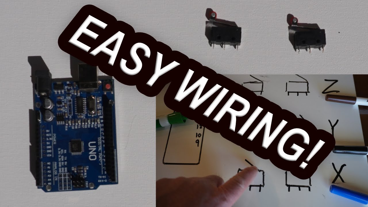
Open the video on YouTube if the embedded player is unavailable.
Frequently asked questions
Can the same CNC limit switch be used for homing and travel limits?
Sometimes. Many controllers support a shared home-and-limit input, but the homing sequence, polarity, back-off behavior, and fault response must be configured for that arrangement. Follow the controller’s official documentation and validate every axis.
Should a CNC limit switch use normally open or normally closed contacts?
Choose the contact arrangement from the complete fault-detection strategy. Normally closed wiring can help some conventional systems detect an open circuit, but it is not automatically fail-safe. Review the controller input design and any applicable safety requirements.
How far should the limit switch be from the CNC hard stop?
There is no universal distance. It must exceed the worst-case stopping and coast distance with an engineering margin, while accounting for speed, load, drive behavior, controller delay, actuator movement, and bracket deflection. Verify it by controlled testing.
Is a CNC limit switch an emergency stop?
No. A conventional position switch may provide a travel signal, but an emergency-stop or safety function requires an appropriate risk assessment, control architecture, components, and validation. Do not treat a general-purpose limit input as the machine’s only safeguard.
Why does the CNC limit input trigger when the spindle starts?
Investigate electrical noise, grounding, shielding, cable separation, contact bounce, and input settings. Correct physical wiring and interference problems before relying on additional software filtering.