
Door Limit Switch for Lifts selection begins with the installed mechanism and the real control input. Record door travel, target position, actuator direction, mounting tolerance, and controller contact logic before asking for a model review. This is component selection for position and travel detection only. It does not claim a lift locking device, regulatory compliance, or completed safety redundancy.
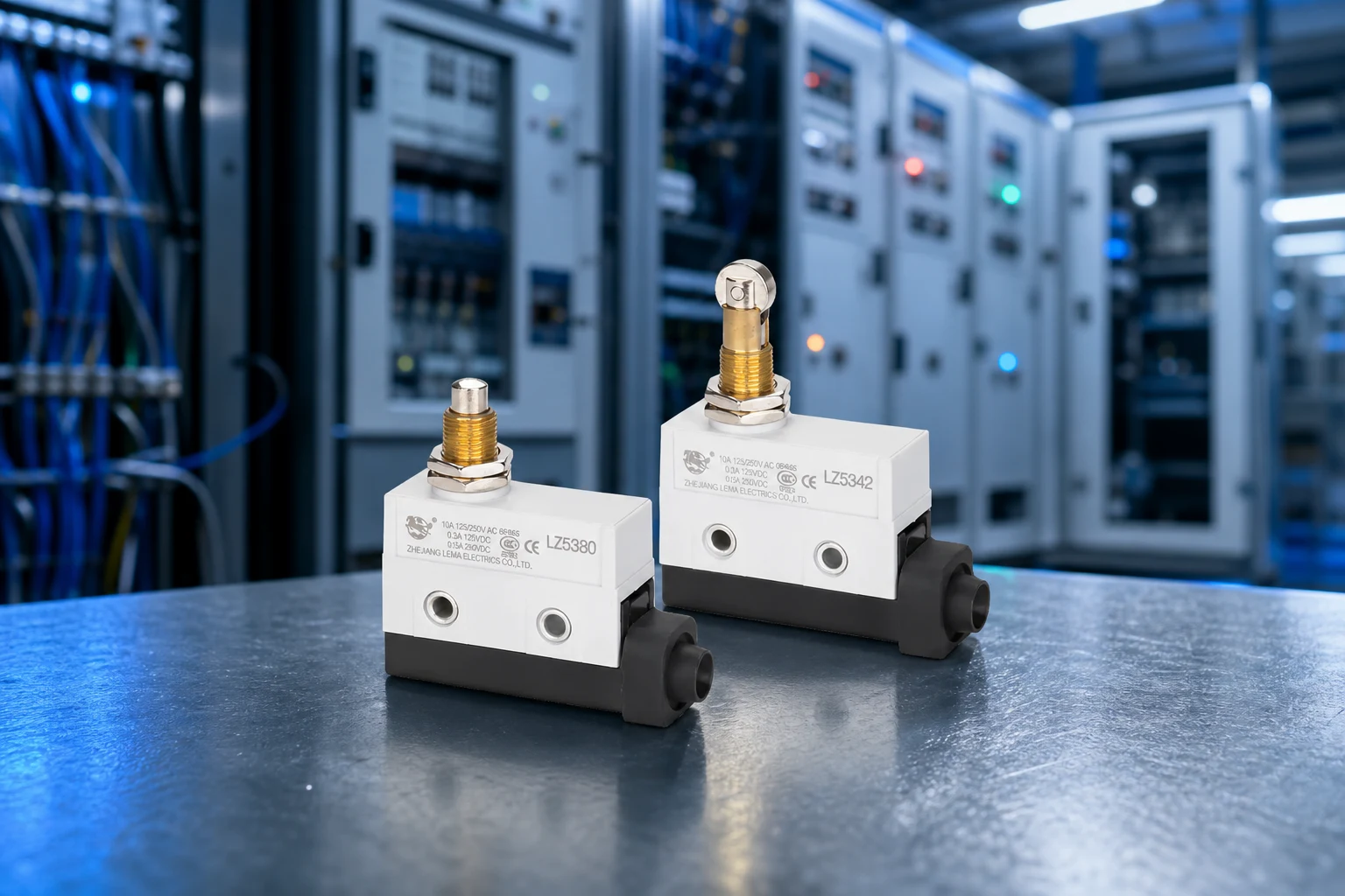
Part 1. What does a door limit switch do in lift equipment?
Start with the required position signal, not the product label. The application drawing should show the moving feature, the state to be reported, and the consequence of a missed or early signal. Use the LEMA Limit Switch product line as a category route, then compare the final candidate with its model documentation.
| Selection field | Input to document | Why it matters |
|---|---|---|
| Position | Target point and tolerance | Defines the required signal window |
| Mechanism | Approach, travel, clearance, and side load | Controls actuation repeatability |
| Circuit | Contact state, voltage, load, and interface | Frames electrical review |
| Environment | Contamination, vibration, temperature, and service access | Frames validation conditions |
Part 2. How should door travel and target positions be defined?
Translate the motion into measurable positions. Identify the normal approach direction, the operating window, the release path, and every tolerance that can move the trip point. A layout review should also record whether adjustment is available and who controls it during installation.
For a roller-driven mechanism, the roller limit switch applications guide can help frame the actuator-path discussion. It does not replace the drawing and model review for this application.
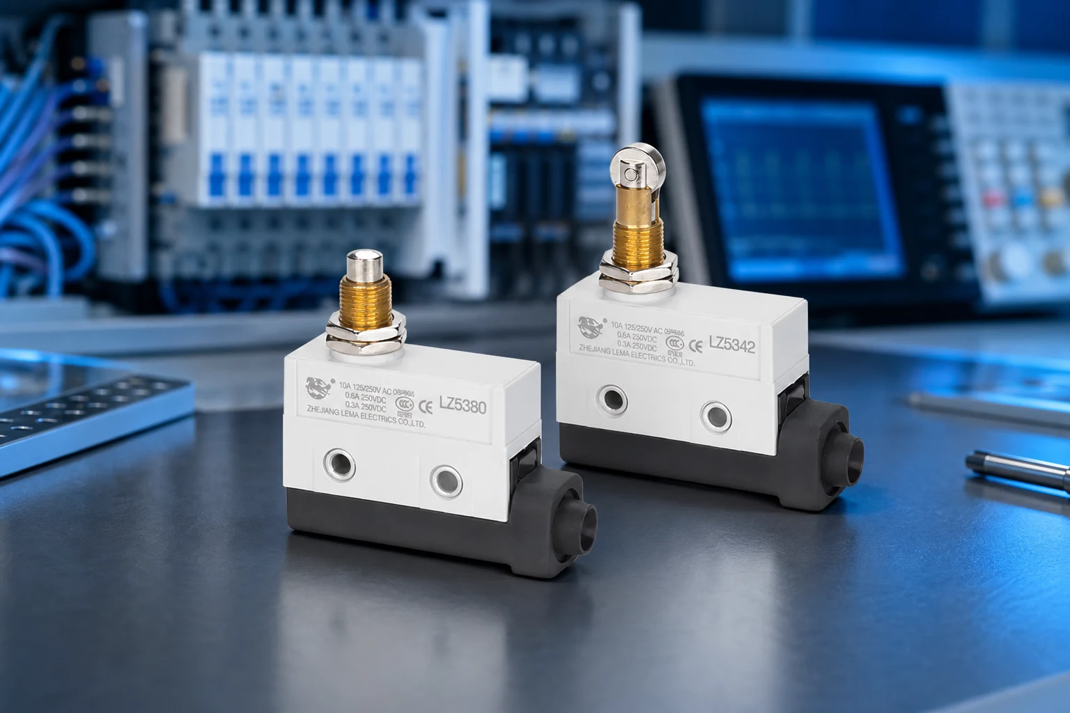
Part 3. Which actuator and mounting details matter?
Mounting must keep the actuator path aligned through the full operating range. Document bracket stiffness, fastener position, stop clearance, cable routing, and access for inspection. Side load or uncontrolled extra travel can change the operating point even when the nominal drawing appears correct.
Part 4. How should contact logic and controller inputs be reviewed?
Review the actual interface with the selected model documentation. Record the required contact state, voltage, current, load type, inrush, switching frequency, and controller input. A nominal value alone does not describe the installed electrical duty.
| Validation check | Question | Risk if missed |
|---|---|---|
| Position | Does the full tolerance stack reach the intended window? | Late, early, or missed signal |
| Actuation | Is clearance maintained through the motion? | Uncontrolled travel or side load |
| Electrical duty | Is the controller interface documented? | Unsuitable contact use |
| Installation | Are cable and service conditions controlled? | Damage during operation or maintenance |
Part 5. What should installation validation cover?
Validate the production-intent assembly, including the moving mechanism, bracket, actuator, harness, and control input. Test nominal and tolerance-extreme conditions and document the revalidation trigger when a mating part, bracket, cable route, or control setting changes.
- Check free, operating, and release positions.
- Inspect clearance, side load, and actuator approach.
- Review the installed circuit duty.
- Define inspection access and change-control ownership.
Part 6. What belongs in the RFQ and Fit Boundary?
RFQ input checklist
- Required position function and contact state
- Load, inrush, voltage, current, and controller input
- Motion drawing, actuator path, mounting, and terminal or harness plan
- Environment, validation method, annual volume, and sample timing
Fit Boundary
Component selection needs documented application inputs. It cannot establish a complete system-level result.
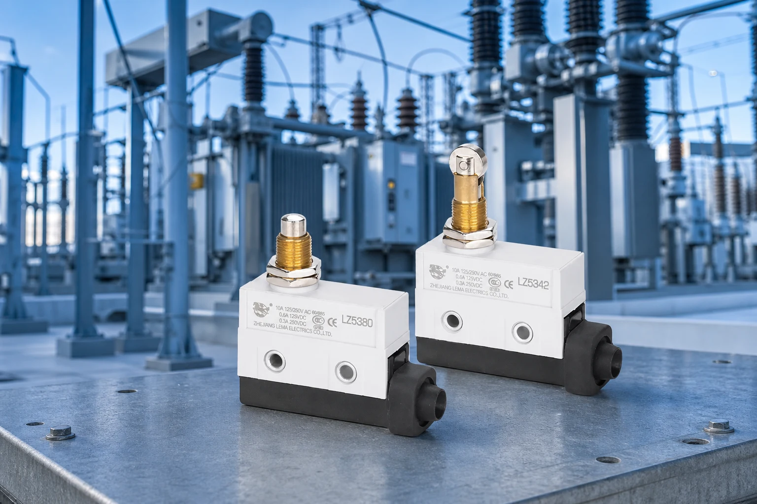
Part 7. How can LEMA support a lift-door inquiry?
Use the LEMA Limit Switch product line as a public starting point for an inquiry. Supply the motion drawing, electrical interface, environmental exposure, validation target, volume, and sample timing so the discussion can be tied to documented model information.
Product recommendation: It is a public route for discussing a position-sensing component with the application inputs attached. Do not select a component solely from an application label.
Send a limit-switch RFQ with the complete application package.
FAQs
What is a door limit switch for lifts?
It is a component used to report a defined mechanical position to a control system. Final suitability depends on the selected model documentation and the installed conditions.
Is a position switch a lift door lock?
Set the application’s target position, approach direction, tolerance, and release condition first, then validate the installed mechanism against the selected model information.
Which travel data should be supplied?
Provide the required motion, circuit logic, and mechanical layout. Do not infer system behavior from a general component label.
How should contact logic be reviewed?
Include the moving-part drawing, travel window, actuator approach, mounting tolerance, clearance, and expected inspection access.
Does this guide establish safety redundancy?
No. Confirm the complete application with responsible system engineering and the selected model documentation.
What belongs in a lift-door switch RFQ?
Provide the required function, contact state, circuit duty, motion drawing, mounting plan, environment, validation target, volume, and sample timing.