IEC C14 and C20 are grounded appliance inlets from the IEC 60320 family, but they are different interfaces and are not interchangeable. C14 mates with a C13 cord connector; C20 mates with a C19 connector. C20 is the larger choice used when the equipment input current exceeds what an approved C14 implementation can provide. The final rating is never selected by shape alone: check the exact inlet, cord set, fuse, wiring, terminal, ambient temperature, approvals and destination-market rules as one power-entry system.
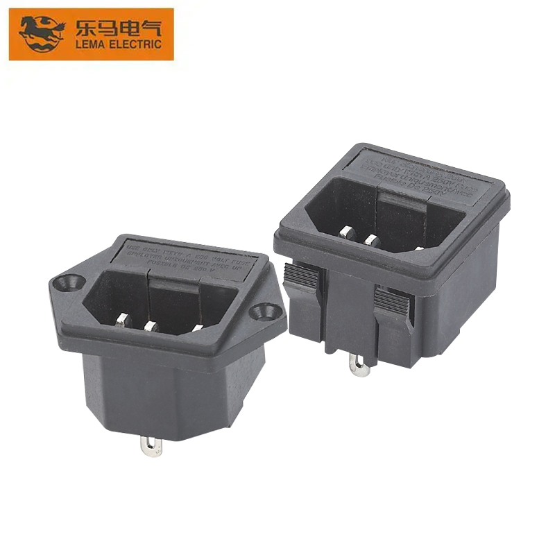
This C20 vs C14 inlet comparison is for OEM equipment design. LEMA’s current product-image library provides a C14-style IPZ inlet reference, so the photographs below deliberately do not claim to show a LEMA C20 product.
Connector identities and mating pairs
The equipment-side male appliance inlet is designated C14 or C20; the cord-side female connector is C13 or C19 respectively. The different outlines help prevent an unintended mating combination. IEC 60320-1 sets general appliance-coupler requirements, while IEC 60320-3 contains the standard sheets and gauges that define dimensional compatibility. The current IEC 60320-1 publication applies to appliance couplers integrated into equipment, and IEC 60320-3 covers the standard dimensions.
| Decision point | C14 inlet | C20 inlet | OEM action |
|---|---|---|---|
| Mating cord connector | C13 | C19 | Specify both inlet and approved cord set |
| Physical interface | Smaller standard-sheet geometry | Larger, differently keyed geometry | Use the exact manufacturer cutout drawing |
| Current class | Common lower-current equipment input | Higher-current IEC 60320 option | Use the marked/approved rating for market and temperature |
| Typical system impact | Smaller cutout and cord ecosystem | Larger inlet, cord and conductor requirements | Review fuse, terminals, wire gauge and thermal rise together |
| Direct substitution | No; connector, cutout and cord set differ | Requalify the complete power-entry design | |
A common shorthand describes C14 as a 10 A international interface and C20 as a 16 A international interface, with different approved values possible in North American use. Those labels do not authorize an OEM to print that value on every part. Interpower’s technical explanation notes that a C14 cannot simply be called a 20 A inlet; the higher-current sheet style is C20. Always use the actual component’s certification file and markings.
Choose by equipment input current, not the appliance name
Start from the equipment’s worst-case continuous input current over the full input-voltage range, efficiency range and operating modes. Include startup behavior where it affects fuse, connector or terminal selection, but do not size the inlet from a brief inrush value alone without the applicable component rules. Apply the product-safety standard for the equipment, national deviations and the relevant cord-set requirements. If the result fits within the approved C14 system under the real ambient and temperature rise, C14 may minimize panel space and cord cost. If it does not, move to a suitable higher-current interface rather than relabeling a smaller one.
The connector is only one link. An inlet rated for a higher current cannot compensate for an undersized internal conductor, a lower-rated switch, fuse holder, filter, quick-connect terminal or PCB trace. Conversely, choosing C20 does not require the equipment to draw the full interface rating; it may provide margin or match an established rack power-distribution ecosystem. Document why the interface was selected.
Calculate input current from the worst permitted input voltage and the maximum credible input power, then validate it by test. Nameplate output power is not necessarily input power because conversion efficiency, auxiliary loads and operating modes matter. If redundant power supplies share the load, also assess the single-supply fault condition. The protective device must tolerate permitted startup current without allowing the connector, terminals or conductors to exceed their approved conditions.
Mechanical design differences affect the enclosure
C20 generally requires more panel area and a different cutout. Never enlarge a C14 cutout from a catalog thumbnail. Obtain the exact drawing for the selected snap-in or flange-mount variant, including panel thickness, corner radius, tolerances, mounting-hole spacing, insertion direction and rear clearance. The cord connector also needs clearance for insertion, withdrawal and cable bend radius. In rack equipment, check interference with adjacent outlets and retention hardware.
Snap-in tabs depend on a permitted panel-thickness range and edge condition. A flange inlet needs fasteners, torque and creepage/clearance review around the mounting features. Neither method is automatically “better”; choose the method that survives production tolerances and mechanical loads. Our power-socket panel-mount guide gives the mechanical workflow, while the C14 power-socket guide explains the established lower-current interface without replacing a product drawing.
Build a cutout coupon before releasing the enclosure. Check insertion force, tab engagement or fastener seating, accessible sharp edges, rear terminal clearance and cord insertion with the intended panel finish. Powder coat, plating and molded-wall draft can shift the effective thickness. A successful CAD fit does not prove that production parts will retain the inlet under cord pull.
Temperature and the complete power-entry path
IEC 60320 ratings depend on standardized conditions and the approved component. Ambient heat inside the enclosure, contact temperature, conductor termination and airflow can change the thermal result. The latest IEC 60320-1 edition includes requirements addressing couplers intended above a specified ambient range; that does not make every inlet suitable for a hot appliance. C14/C13 and C20/C19 are commonly classed as cold-condition couplers. If the application requires a hot-condition interface, evaluate the appropriate IEC sheet style and the equipment standard rather than assuming C20 solves temperature exposure.
Perform the required temperature-rise and abnormal-condition evaluations on the production configuration. Use the specified crimp terminal, wire size, insulation, torque and fuse. A loose quick-connect or incorrect receptacle width can create localized heating even when the nominal current is within the inlet rating. Include cord quality and contact retention in incoming inspection.

Protective earth, line and neutral
Both C14 and C20 are grounded three-contact interfaces. Protective earth must be routed and terminated according to the equipment safety design, normally so it is not dependent on a removable functional conductor. Line and neutral orientation, fuse placement, switch placement and conductor identification follow the relevant equipment standard and destination requirements. Do not publish a generic rear-view diagram without defining whether it is viewed from the mating face or terminal side; mirrored diagrams are a frequent assembly error.
For a design with an integrated fuse and switch, see the C14 fused and switched inlet guide. For connector naming, the C13 versus C14 guide distinguishes the cord connector from the equipment inlet. The three-pin socket symbol guide helps document line, neutral and earth. These pages complement this capacity/interface decision rather than target the same search intent.
When C14 is usually the better fit
- The verified equipment current and thermal test fit the approved C14 system.
- Panel space, global cord availability and service familiarity matter.
- The product already uses a qualified C13 cord-set ecosystem.
- The selected LEMA inlet has the needed mounting, terminal and approval combination.
When to evaluate C20
- The equipment current is beyond the permitted C14 implementation.
- A rack or power-distribution design is standardized around C19/C20.
- The larger cord and connector retention suit the mechanical requirement.
- The complete internal wiring, protection and thermal design are sized for that interface.
Do not choose C20 only because it looks “industrial,” and do not keep C14 only to save panel area. The inlet communicates which cord can mate with the equipment, so it is part of the safety and service architecture.
Service documentation should state the required cord connector, conductor capacity, regional plug and approval. Replacement cords should not be selected only because they physically mate. During final inspection, verify earth continuity, polarity where applicable, fuse value, terminal retention and the exact inlet marking against the bill of materials.
OEM verification and RFQ checklist
Provide nominal voltage, frequency, maximum input current, destination markets, equipment safety standard, ambient and internal temperature, appliance class, required approvals, cord-set requirement, panel material and thickness, mounting style, cutout drawing, terminal type, internal wire specification, fuse and switch arrangement, earth-bonding method and annual volume. Ask for the exact component drawing and certification record. LEMA’s IPZ series AC power socket is a relevant C14-style starting point; confirm availability and specifications directly. This article does not represent that LEMA currently offers a C20 inlet.
FAQ
Can a C13 cord plug into a C20 inlet?
No. C14 pairs with C13, while C20 pairs with C19. The interfaces have different standardized geometry and should not be adapted casually.
Is every C14 inlet rated 10 A and every C20 rated 16 A?
Those are common IEC current classes, but the legally usable value depends on the exact approved component, region, temperature and equipment conditions. Read the marking and certification data.
Can I replace C14 with C20 without redesigning the equipment?
No. The cutout, connector, cord set, internal conductors, terminals, fuse, switch and thermal validation may all change. Treat it as a power-entry redesign.
Does C20 provide a higher temperature rating?
Not automatically. Current capacity and temperature class are separate selections. Verify the standard sheet and approved temperature rating for the exact inlet and connector.
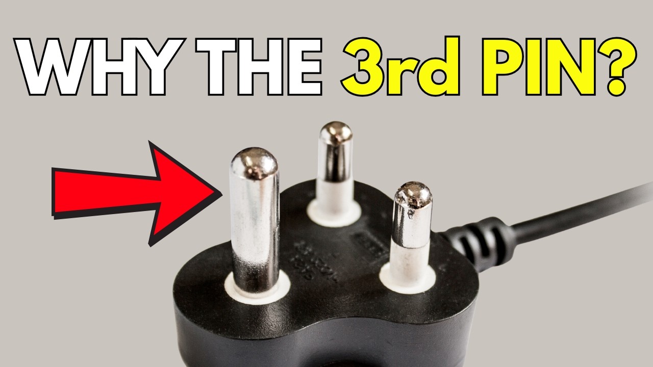
Video: why the third contact matters
This neutral explainer covers the purpose of the earth contact in a three-pin supply system. It provides grounding context; it does not replace IEC 60320 dimensions or equipment certification.