CENTRE D’ACTUALITÉS LEMA

Actualités et blog

Centre d’actualités

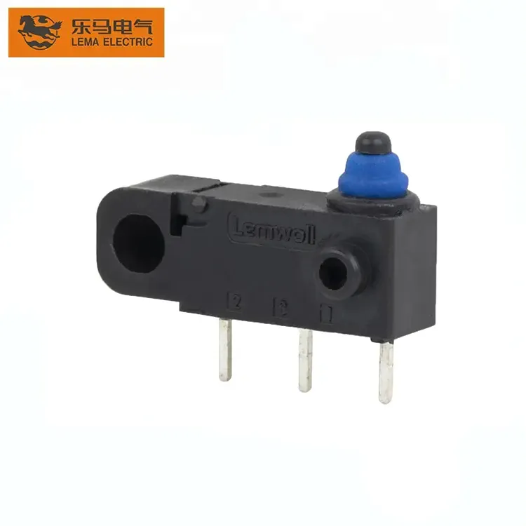
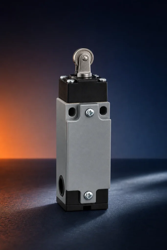
Retour d’information sur la position par interrupteur de fin de course magnétique pour les motorisations de portail
Blogue LEMA Électrique

Retour d’information sur la position par interrupteur de fin de course magnétique pour les motorisations de portail

Magnetic Limit Switch for Gate Opener decisions begin with the installed mechanism, not a catalogue label. Define the actuator path, circuit duty, environment, mounting, and validation target before requesting a final model review. Similar-looking parts can have different operating windows, terminals, and documented limits. ContentsPart 1. Define the position-feedback jobPart 2. Map travel and mountingPart 3. Set the environmental boundaryPart 4. Document circuit dutyPart 5. Plan validation and fitPart 6. Route a documented inquiryFAQsReferencesPart 1. Define the position-feedback job Describe the state that must change, the moving feature that creates it, and the consequence of a late, early, or missing signal. This keeps a mechanical position question separate from assumptions about a particular series. Decision fieldInput to documentWhy it mattersFunctionFree and operated statesPrevents reversed control logicMechanismTravel, force, and side loadControls repeatable actuationCircuitVoltage, current, load, and inrushFrames contact reviewEnvironmentContamination, vibration, service accessFrames validation Part 2. Map travel and mounting Put free position, operating position, release, maximum travel, and bracket tolerances on one drawing. The same drawing should identify the approach direction and any side load transferred by a cam, button, linkage, magnet, or stop. Use the industrial micro switch selection guide when the mechanical interface also needs a broader panel review. Part 3. Set the environmental boundary Translate site conditions into exposure inputs: dust, splash, cleaning method, temperature variation, vibration, cable movement, and access for service. A surrounding enclosure does not establish the capability of every component interface inside it. Record the target exposure and the test method rather than inferring a result from a product family name. Part 4. Document circuit duty Contact suitability depends on the actual circuit. Capture voltage, current, load type, inrush, switching frequency, and controller input...

Lire la suite
Wiring a Double Pole Micro Switch in Appliance Control
Blogue LEMA Électrique

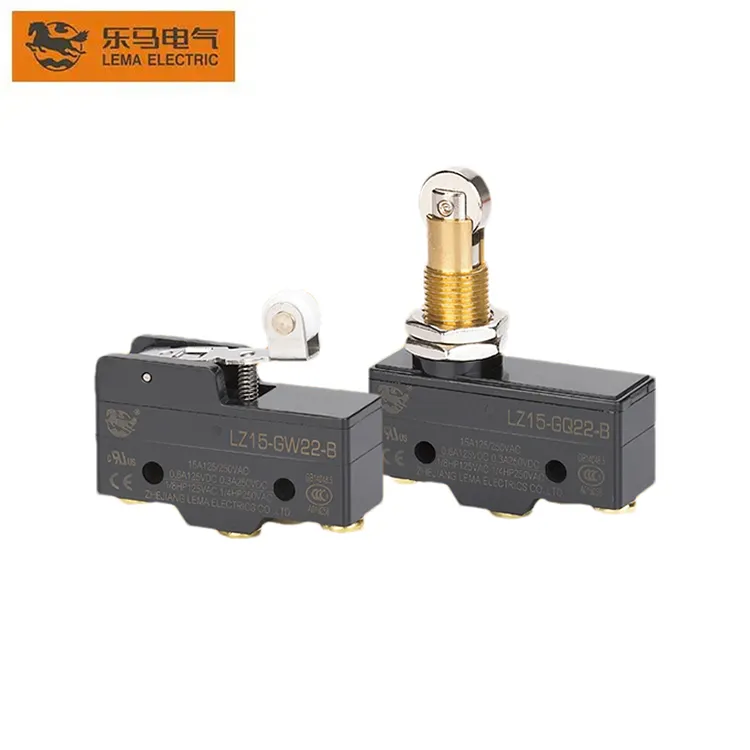
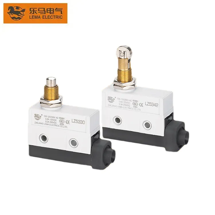
Wiring a Double Pole Micro Switch in Appliance Control

A double pole micro switch changes two separate circuits with one snap action. That single mechanical event can open line and neutral together, or drive a load and its indicator in step. Wire it from a two-circuit drawing, never from terminal appearance. ContentsPart 1. What does double pole mean in a micro switch?Part 2. Which appliance scenarios need two switched circuits?Part 3. How should both circuits be drawn before wiring?Part 4. Which terminal and simultaneity checks matter?Part 5. How does load per pole change the review?Part 6. What belongs in the RFQ and Fit Boundary?Part 7. How can LEMA support a double pole inquiry?FAQsReferencesPart 1. What does double pole mean in a micro switch? Double pole construction places two contact sets on one common actuator. Each pole keeps its own terminals and its own circuit, while the mechanism forces both to change state in the same actuation. ConfigurationPolesTypical useSPST / SPDTOneSingle sensing or control pathDPSTTwo, on-offSwitching two conductors togetherDPDTTwo, changeoverTwo circuits that each need NO and NC paths Confirm the configuration code against the LEMA Micro Switch product line documentation for the series in question, since families differ in which poles they offer. Part 2. Which appliance scenarios need two switched circuits? Appliance control creates the common cases. A door interlock may need to cut power and signal the controller in one motion, while a heating product may switch the element circuit and a status lamp together. Single-circuit examples of the same discipline appear in the refrigerator door switch guide, where one pole handles the sensing task alone. Part 3. How should both circuits be drawn before wiring? Draw each circuit end to end before touching terminals: source, load, protection,...

Lire la suite
Selecting a Plunger Limit Switch for Machine-Tool Position Sensing
Blogue LEMA Électrique

Selecting a Plunger Limit Switch for Machine-Tool Position Sensing

Plunger Limit Switch decisions begin with the installed mechanism, not a catalogue label. Define the actuator path, circuit duty, environment, mounting, and validation target before requesting a final model review. Similar-looking parts can have different operating windows, terminals, and documented limits. ContentsPart 1. Define the position-feedback jobPart 2. Map travel and mountingPart 3. Set the environmental boundaryPart 4. Document circuit dutyPart 5. Plan validation and fitPart 6. Route a documented inquiryFAQsReferencesPart 1. Define the position-feedback job Describe the state that must change, the moving feature that creates it, and the consequence of a late, early, or missing signal. This keeps a mechanical position question separate from assumptions about a particular series. Decision fieldInput to documentWhy it mattersFunctionFree and operated statesPrevents reversed control logicMechanismTravel, force, and side loadControls repeatable actuationCircuitVoltage, current, load, and inrushFrames contact reviewEnvironmentContamination, vibration, service accessFrames validation Part 2. Map travel and mounting Put free position, operating position, release, maximum travel, and bracket tolerances on one drawing. The same drawing should identify the approach direction and any side load transferred by a cam, button, linkage, magnet, or stop. Use the industrial micro switch selection guide when the mechanical interface also needs a broader panel review. Part 3. Set the environmental boundary Translate site conditions into exposure inputs: dust, splash, cleaning method, temperature variation, vibration, cable movement, and access for service. A surrounding enclosure does not establish the capability of every component interface inside it. Record the target exposure and the test method rather than inferring a result from a product family name. Part 4. Document circuit duty Contact suitability depends on the actual circuit. Capture voltage, current, load type, inrush, switching frequency, and controller input behavior, then compare...

Lire la suite
Adapter les types d’actionneurs au mouvement du mécanisme du fabricant d’équipement d’origine (OEM)
Blogue LEMA Électrique

Adapter les types d’actionneurs au mouvement du mécanisme du fabricant d’équipement d’origine (OEM)

Actuator choice is a motion-matching exercise, not a styling decision. Lever, roller lever, plunger, and button actuators translate the same snap mechanism to different travel directions, forces, and tolerances. Start from how the moving part approaches the switch, then keep the operating point stable. ContentsPart 1. How does an actuator change switch behavior?Part 2. When is a plain lever or long lever right?Part 3. When do roller actuators earn their cost?Part 4. How do plunger and button styles behave?Part 5. Which mounting and tolerance inputs decide repeatability?Part 6. What belongs in the RFQ and Fit Boundary?Part 7. How can LEMA support an actuator inquiry?FAQsReferencesPart 1. How does an actuator change switch behavior? The actuator converts mechanism motion into internal plunger travel. Each style changes three things at once: the force the mechanism must supply, the travel required to operate, and the sensitivity to misalignment. ActuatorMotion it suitsWatch-outPin plungerDirect in-line pressTravel must be tightly controlledLeverCams and rotating partsForce capability drops as length growsRoller leverSliding cam surfacesSide load on rough profilesButtonPanel or operator pressNeeds overtravel protection Anchor the review in the LEMA Micro Switch product line so each candidate style maps to a documented series. Part 2. When is a plain lever or long lever right? Plain levers absorb approach-angle variation and reduce the force a mechanism must deliver. Longer arms trade operating force against a wider tolerance on the operating position, so the drawing must show where in the stroke the circuit changes state. For extended-reach cases with cams or linkages, the long arm actuator selection guide covers arm length, force, and repeatability in detail. Part 3. When do roller actuators earn their cost? Rollers replace sliding friction with rolling contact,...

Lire la suite
Comment formuler une demande de renseignements sur un micro-interrupteur miniature de la série SW10
Blogue LEMA Électrique

Comment formuler une demande de renseignements sur un micro-interrupteur miniature de la série SW10

SW10 Series Mini Micro Switch decisions begin with the installed mechanism, not a catalogue label. Define the actuator path, circuit duty, environment, mounting, and validation target before requesting a final model review. Similar-looking parts can have different operating windows, terminals, and documented limits. ContentsPart 1. Define the position-feedback jobPart 2. Map travel and mountingPart 3. Set the environmental boundaryPart 4. Document circuit dutyPart 5. Plan validation and fitPart 6. Route a documented inquiryFAQsReferencesPart 1. Define the position-feedback job Describe the state that must change, the moving feature that creates it, and the consequence of a late, early, or missing signal. This keeps a mechanical position question separate from assumptions about a particular series. Decision fieldInput to documentWhy it mattersFunctionFree and operated statesPrevents reversed control logicMechanismTravel, force, and side loadControls repeatable actuationCircuitVoltage, current, load, and inrushFrames contact reviewEnvironmentContamination, vibration, service accessFrames validation The supplied photographs show micro switches for visual context; they are not represented as SW10 products. Part 2. Map travel and mounting Put free position, operating position, release, maximum travel, and bracket tolerances on one drawing. The same drawing should identify the approach direction and any side load transferred by a cam, button, linkage, magnet, or stop. Use the industrial micro switch selection guide when the mechanical interface also needs a broader panel review. Part 3. Set the environmental boundary Translate site conditions into exposure inputs: dust, splash, cleaning method, temperature variation, vibration, cable movement, and access for service. A surrounding enclosure does not establish the capability of every component interface inside it. Record the target exposure and the test method rather than inferring a result from a product family name. Part 4. Document circuit duty Contact suitability depends...

Lire la suite
Élaboration d’une demande de devis (RFQ) pour un micro-interrupteur OEM sur mesure
Blogue LEMA Électrique

Élaboration d’une demande de devis (RFQ) pour un micro-interrupteur OEM sur mesure

A custom micro switch quote is only as good as the inputs behind it. Suppliers quote fastest when the RFQ defines actuator geometry, terminal style, electrical duty, sealing, validation expectations, and volumes in one document. Missing fields turn into assumptions, and assumptions surface later as sample rejections. ContentsPart 1. What does custom mean for a micro switch order?Part 2. Which actuator inputs should the RFQ define?Part 3. Which terminal and lead options need decisions?Part 4. How should contact duty and sealing be specified?Part 5. How do volumes and sample stages shape the quote?Part 6. What belongs in the RFQ package and Fit Boundary?Part 7. How can LEMA respond to a custom inquiry?FAQsReferencesPart 1. What does custom mean for a micro switch order? Custom rarely means a new mechanism from scratch. Most OEM requests combine a documented base series with a specific lever, terminal, lead, force option, or packaging arrangement. Framing the request this way keeps tooling cost down and shortens sampling. Request levelTypical contentQuote impactCatalog optionStandard series codeFastest sampling pathConfigured optionLever length, force, or terminal variantModerate engineering reviewTooled customNew geometry or sealed assemblyTooling plus a validation plan Browse the LEMA Micro Switch product line first so the RFQ references a real series family instead of a generic description. Part 2. Which actuator inputs should the RFQ define? Actuator geometry drives most configured orders. Record travel direction, available stroke, force budget, side-load risk, and the position in travel where the state change must occur. A drawing beats a text description. Even a hand sketch with datum references removes most of the clarification loops that stretch quoting timelines. Part 3. Which terminal and lead options need decisions? Terminal style decides the downstream...

Lire la suite
Integrating a Side-Actuated Tact Micro Switch in a Compact Panel
Blogue LEMA Électrique

Integrating a Side-Actuated Tact Micro Switch in a Compact Panel

Tact Micro Switch Side Actuated decisions begin with the installed mechanism, not a catalogue label. Define the actuator path, circuit duty, environment, mounting, and validation target before requesting a final model review. Similar-looking parts can have different operating windows, terminals, and documented limits. - FAQs ContentsPart 1. Define the position-feedback jobPart 2. Map travel and mountingPart 3. Set the environmental boundaryPart 4. Document circuit dutyPart 5. Plan validation and fitPart 6. Route a documented inquiryPart 1. Define the position-feedback job Describe the state that must change, the moving feature that creates it, and the consequence of a late, early, or missing signal. This keeps a mechanical position question separate from assumptions about a particular series. Decision fieldInput to documentWhy it mattersFunctionFree and operated statesPrevents reversed control logicMechanismTravel, force, and side loadControls repeatable actuationCircuitVoltage, current, load, and inrushFrames contact reviewEnvironmentContamination, vibration, service accessFrames validation Browse the LEMA Micro Switch product line for category routing, then keep the final choice tied to the panel drawing. Part 2. Map travel and mounting Put free position, operating position, release, maximum travel, and bracket tolerances on one drawing. The same drawing should identify the approach direction and any side load transferred by a cam, button, linkage, or stop. Use the industrial micro switch selection guide when the mechanical interface also needs a broader panel review. Important: A side-actuated tact switch is not automatically suitable for power switching or safety-lock functions. Confirm the circuit duty and mechanism travel against the selected model documentation before release — see <a href="https://webstore.iec.ch/en/publication/66912">Champ d’application de la publication IEC 61058-1</a>. Part 3. Set the environmental boundary Translate site conditions into exposure inputs: dust, splash, cleaning method, temperature variation, vibration, cable movement, and access for...

Lire la suite
Choosing Between Gold and Silver Micro Switch Contacts
Blogue LEMA Électrique

Choosing Between Gold and Silver Micro Switch Contacts

Gold plated contacts and silver contacts solve different micro switch problems. Gold plating protects low-energy signal circuits from oxide and film buildup, while silver alloys carry higher currents and tolerate arcing. Match the contact system to the real circuit before locking a series code. ContentsPart 1. Why does contact material matter in a micro switch?Part 2. Where do gold plated contacts fit best?Part 3. Where do silver contacts fit best?Part 4. How do load level and inrush drive the choice?Part 5. Which environmental factors change contact behavior?Part 6. What belongs in the RFQ and Fit Boundary?Part 7. How can LEMA support a contact material inquiry?Part 1. Why does contact material matter in a micro switch? Contact material sits at the center of switching reliability. A snap-action mechanism can be mechanically perfect and still fail its circuit when the contact surface no longer conducts predictably at the applied signal level. Decision fieldWhat to recordEffect on material choiceSignal levelOpen-circuit voltage and switched currentDetermines whether film resistance mattersLoad typeResistive, inductive, or lamp behaviorChanges arc energy at the contactSwitching rateOperations per hour and per lifeAffects heating and material transferAtmosphereSulfur sources, humidity, sealingDrives tarnish and film growth Route early browsing through the LEMA Micro Switch product line, and treat catalog material notes as a starting point rather than a project rating. Part 2. Where do gold plated contacts fit best? Gold resists oxidation and sulfide films, which keeps contact resistance stable when the circuit cannot generate enough energy to break through a film. That behavior makes gold plating the usual candidate for logic inputs, controller sensing lines, and low milliamp loads. Signal-side thinking also applies when a switch replaces a sensor. The micro switch and...

Lire la suite
Planning a Long Life Micro Switch for OEM Duty Cycles
Blogue LEMA Électrique

Planning a Long Life Micro Switch for OEM Duty Cycles

Long Life Micro Switch selection starts with the installed duty, not a broad catalog label. Define the mechanism, circuit, environment, mounting, and validation target before approving a sample. A component can look similar while carrying different terminal, travel, contact, or test limits. ContentsPart 1. What does long life mean for a micro switch?Part 2. Which duty-cycle fields should be defined first?Part 3. How do contact load and inrush affect life planning?Part 4. Why do actuator travel and overtravel matter?Part 5. Which environmental and assembly factors shorten service life?Part 6. What belongs in the RFQ and Fit Boundary?Part 7. How can LEMA support a cycle-life inquiry?Part 1. What does long life mean for a micro switch? The useful definition is functional: the selected switch must repeat the intended state change in the real mechanism and circuit. Start with the application drawing, then compare the actual model documentation rather than relying on an application name alone. Selection fieldInput to documentWhy it mattersFunctionFree and operated statePrevents incorrect circuit behaviorMechanismTravel, force, and side loadControls reliable actuationCircuitVoltage, current, load, inrushControls contact suitabilityEnvironmentContamination, vibration, temperature, ingressDefines validation conditions Use the LEMA Micro Switch product line for category routing, then confirm the final option from the model information. Part 2. Which duty-cycle fields should be defined first? Document where the moving feature meets the actuator and how the bracket controls travel. The drawing should show free position, operating position, release, maximum travel, and clearance to adjacent parts. Where a remote cam or linkage needs extra reach, review the long-arm mechanical actuation approach before selecting a lever arrangement. Part 3. How do contact load and inrush affect life planning? Translate the application environment into concrete exposure inputs: dust,...

Lire la suite
Sélection d’un microrupteur industriel pour les panneaux OEM
Blogue LEMA Électrique

Sélection d’un microrupteur industriel pour les panneaux OEM

Industrial Micro Switch selection starts with the installed duty, not a broad catalog label. Define the mechanism, circuit, environment, mounting, and validation target before approving a sample. A component can look similar while carrying different terminal, travel, contact, or test limits. ContentsPart 1. What makes a micro switch industrial?Part 2. Which actuator and mounting inputs matter?Part 3. How should ingress and enclosure exposure be defined?Part 4. How do circuit load and cycle demands affect selection?Part 5. Which panel installation checks prevent early failures?Part 6. What belongs in the RFQ and Fit Boundary?Part 7. How can LEMA support an industrial inquiry?Part 1. What makes a micro switch industrial? The useful definition is functional: the selected switch must repeat the intended state change in the real mechanism and circuit. Start with the application drawing, then compare the actual model documentation rather than relying on an application name alone. Selection fieldInput to documentWhy it mattersFunctionFree and operated statePrevents incorrect circuit behaviorMechanismTravel, force, and side loadControls reliable actuationCircuitVoltage, current, load, inrushControls contact suitabilityEnvironmentContamination, vibration, temperature, ingressDefines validation conditions Use the LEMA Micro Switch product line for category routing, then confirm the final option from the model information. Part 2. Which actuator and mounting inputs matter? Document where the moving feature meets the actuator and how the bracket controls travel. The drawing should show free position, operating position, release, maximum travel, and clearance to adjacent parts. Where a remote cam or linkage needs extra reach, review the long-arm mechanical actuation approach before selecting a lever arrangement. Part 3. How should ingress and enclosure exposure be defined? Translate the application environment into concrete exposure inputs: dust, splash, cleaning method, vibration, temperature, service access, and cable movement....

Lire la suite
Micro Switch vs Reed Switch for OEM Position Sensing
Blogue LEMA Électrique

Micro Switch vs Reed Switch for OEM Position Sensing

Micro switches and reed switches solve different sensing problems: one changes state from controlled mechanical movement, while the other changes state from a correctly positioned magnetic field. Select from the installed mechanism, contact/load requirements, mounting tolerance, environmental exposure, and validation plan—not from a generic “non-contact” label. ContentsPart 1. What is the functional difference between micro and reed switches?Part 2. When does mechanical actuation favor a micro switch?Part 3. When does a magnetically actuated reed switch fit better?Part 4. How do contact behavior and load affect the choice?Part 5. Which mounting and environmental checks matter?Part 6. What belongs in the selection RFQ and Fit Boundary?Part 7. How can LEMA support a mechanical-switch inquiry?Part 1. What is the functional difference between micro and reed switches? A micro switch uses a plunger, lever, roller, or button to produce a snap action at a defined mechanical travel. A reed switch is actuated by a magnetic field; its result depends on magnet strength, position, orientation, and the installed gap. Decision fieldMicro switchReed switchActuation inputMechanical travelMagnetic field and gapPrimary integration questionActuator path and overtravelMagnet geometry and repeatabilitySelection evidenceModel drawing and circuit dutySensor/magnet assembly data and circuit duty Part 2. When does mechanical actuation favor a micro switch? A micro switch fits when a moving feature can provide repeatable mechanical travel and the design can control force, side load, and overtravel. Cams, doors, levers, and mechanism end positions are typical examples. For variants of the mechanical interface, compare the button actuator behavior and the long-arm mechanical actuation guides. Part 3. When does a magnetically actuated reed switch fit better? A reed switch can fit when a physical gap or enclosure boundary makes mechanical contact undesirable and the...

Lire la suite
Comment câbler un microrupteur pour un assemblage OEM
Blogue LEMA Électrique

Comment câbler un microrupteur pour un assemblage OEM

Wire a micro switch only after identifying the approved terminals, intended contact state, circuit load, wire route, and isolation method. COM, NO, and NC labels describe a contact relationship; they do not by themselves prove that a component is suitable for every voltage, current, or safety function. ContentsPart 1. What terminals does a micro switch use?Part 2. How do COM, NO, and NC change circuit behavior?Part 3. How should the load and contact rating be checked?Part 4. Which wiring and insulation checks matter?Part 5. How should terminals be connected in production?Part 6. What belongs in the wiring RFQ and Fit Boundary?Part 7. How can LEMA support a terminal inquiry?Part 1. What terminals does a micro switch use? A changeover micro switch commonly has COM, NO, and NC terminals. In the free position, COM connects to one contact path; actuation transfers it to the other. Read the approved drawing and terminal marking for the exact selected model before connecting a production harness. Terminal fieldMeaning to confirmAssembly actionCOMCommon contact nodeMap it to the schematic referenceNOPath closed after actuationVerify the required operated stateNCPath closed before actuationVerify the required free state Start at the LEMA Micro Switch product line, then hold final terminal selection to the model drawing and sample. Part 2. How do COM, NO, and NC change circuit behavior? COM-to-NO is used when the circuit should close at the intended operating point. COM-to-NC is used when the circuit needs continuity before that point. The correct option depends on the system’s required normal state, including what the controller must see if the actuator is not engaged. Do not infer a safe-state function from the terminal label alone. Trace the circuit through its controller...

Lire la suite