CENTRO NOTIZIE LEMA

News e Blog

Centro Notizie

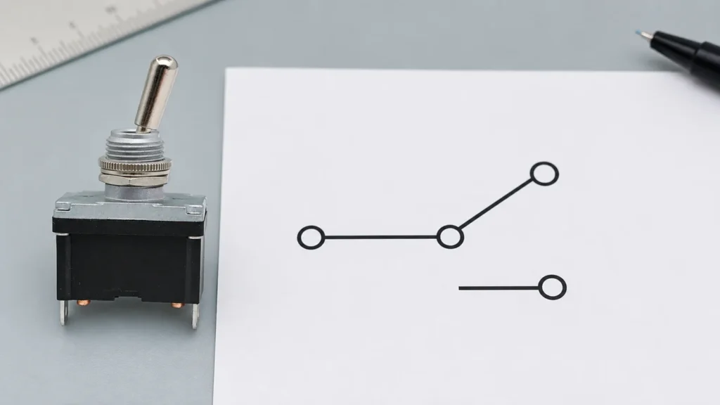
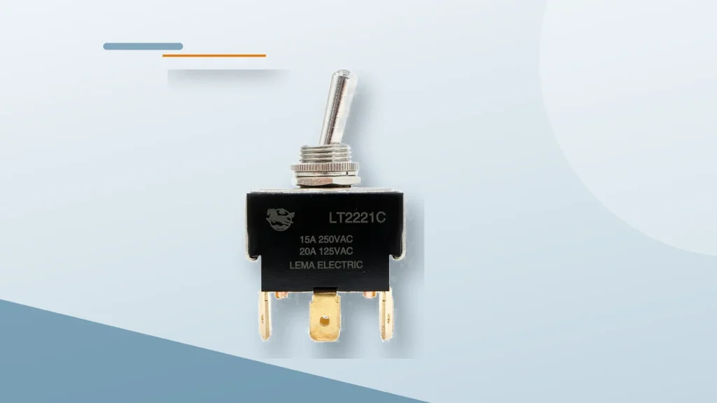
DPST Toggle Switch Wiring for Two-Circuit Isolation
Blog LEMA Electric

DPST Toggle Switch Wiring for Two-Circuit Isolation

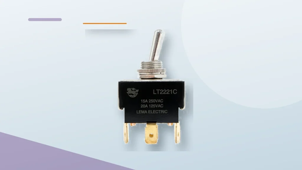
Dpst toggle switch wiring should be selected by matching the electrical function, mechanical interface, environment, and verification plan—not by copying a generic diagram or choosing from appearance alone. A DPST toggle contains two poles that change state together for simple two-circuit on/off isolation. It is not the same as DPDT, which provides two throws per pole. Terminal position varies by model, so continuity must be verified against the manufacturer's diagram before conductors are connected. This guide gives engineers and OEM buyers a practical way to define the requirement, compare samples, and avoid a part that works on the bench but fails after installation. Application-focused view using the matching LEMA product. What the term means in this application A DPST toggle contains two poles that change state together for simple two-circuit on/off isolation. It is not the same as DPDT, which provides two throws per pole. Terminal position varies by model, so continuity must be verified against the manufacturer's diagram before conductors are connected. The first job is to separate the switch's name from its required behavior. Product names are often shortened for search or purchasing, while an engineering drawing defines the contact state, terminal numbering, operating point, allowable travel, mounting reference, and ratings. If those details are missing, two parts with similar names may behave differently. Write the control requirement as a short sequence: the condition before actuation, the physical action that causes actuation, the electrical state after actuation, and the condition that resets it. This sequence prevents confusion between mechanical action and contact logic. It also gives the controls engineer, mechanical designer, buyer, and supplier one shared description to review. Do not treat a catalog current rating as a...

Leggi di più
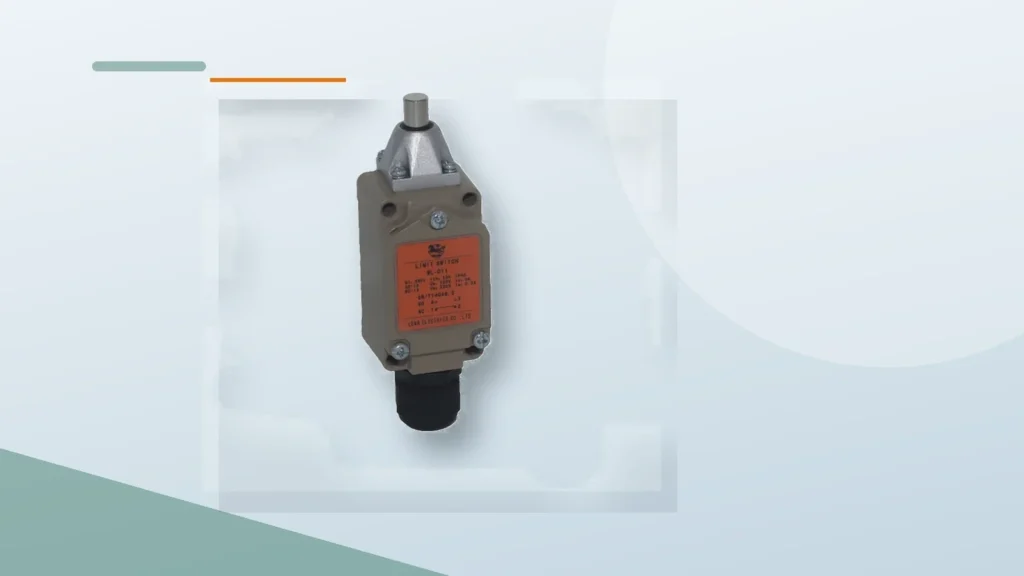
Hermetically Sealed Limit Switch: Uses and Selection Criteria
Blog LEMA Electric

Hermetically Sealed Limit Switch: Uses and Selection Criteria

Hermetically sealed limit switch should be selected by matching the electrical function, mechanical interface, environment, and verification plan—not by copying a generic diagram or choosing from appearance alone. Hermetic sealing uses a sealed envelope intended to prevent gas or moisture exchange through the enclosure. It is different from a boot or ordinary water-resistant housing. Selection must address the actual atmosphere, pressure, temperature cycling, lead sealing, contact load, and evidence for the claimed construction. This guide gives engineers and OEM buyers a practical way to define the requirement, compare samples, and avoid a part that works on the bench but fails after installation. Application-focused view using the matching LEMA product. What the term means in this application Hermetic sealing uses a sealed envelope intended to prevent gas or moisture exchange through the enclosure. It is different from a boot or ordinary water-resistant housing. Selection must address the actual atmosphere, pressure, temperature cycling, lead sealing, contact load, and evidence for the claimed construction. The first job is to separate the switch's name from its required behavior. Product names are often shortened for search or purchasing, while an engineering drawing defines the contact state, terminal numbering, operating point, allowable travel, mounting reference, and ratings. If those details are missing, two parts with similar names may behave differently. Write the control requirement as a short sequence: the condition before actuation, the physical action that causes actuation, the electrical state after actuation, and the condition that resets it. This sequence prevents confusion between mechanical action and contact logic. It also gives the controls engineer, mechanical designer, buyer, and supplier one shared description to review. Do not treat a catalog current rating as a universal permission...

Leggi di più
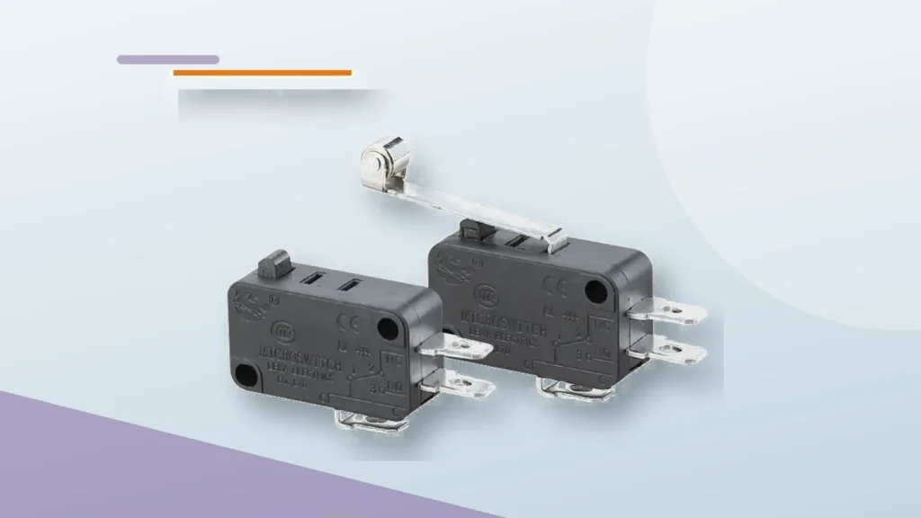
Micro Switch Pretravel, Overtravel and Differential Travel Explained
Blog LEMA Electric

Micro Switch Pretravel, Overtravel and Differential Travel Explained

Micro switch pretravel overtravel differential should be selected by matching the electrical function, mechanical interface, environment, and verification plan—not by copying a generic diagram or choosing from appearance alone. Pretravel is actuator movement before contact transfer; overtravel is the permitted movement after transfer; differential travel is the distance between operate and release points. These terms describe different parts of the motion envelope and should never be substituted for one another on a drawing or inspection report. This guide gives engineers and OEM buyers a practical way to define the requirement, compare samples, and avoid a part that works on the bench but fails after installation. Application-focused view using the matching LEMA product. What the term means in this application Pretravel is actuator movement before contact transfer; overtravel is the permitted movement after transfer; differential travel is the distance between operate and release points. These terms describe different parts of the motion envelope and should never be substituted for one another on a drawing or inspection report. The first job is to separate the switch's name from its required behavior. Product names are often shortened for search or purchasing, while an engineering drawing defines the contact state, terminal numbering, operating point, allowable travel, mounting reference, and ratings. If those details are missing, two parts with similar names may behave differently. Write the control requirement as a short sequence: the condition before actuation, the physical action that causes actuation, the electrical state after actuation, and the condition that resets it. This sequence prevents confusion between mechanical action and contact logic. It also gives the controls engineer, mechanical designer, buyer, and supplier one shared description to review. Do not treat a catalog current...

Leggi di più
IEC C13 vs C14: Connector Differences and Compatibility
Blog LEMA Electric

IEC C13 vs C14: Connector Differences and Compatibility

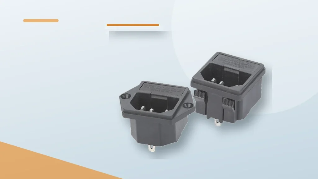
C13 vs c14 should be selected by matching the electrical function, mechanical interface, environment, and verification plan—not by copying a generic diagram or choosing from appearance alone. C13 is a cord connector and C14 is the matching appliance inlet in the common IEC 60320 family. They are complementary parts, not interchangeable names. Compatibility also depends on current, voltage, temperature class, cord construction, approvals, and the equipment's inlet orientation. This guide gives engineers and OEM buyers a practical way to define the requirement, compare samples, and avoid a part that works on the bench but fails after installation. Application-focused view using the matching LEMA product. What the term means in this application C13 is a cord connector and C14 is the matching appliance inlet in the common IEC 60320 family. They are complementary parts, not interchangeable names. Compatibility also depends on current, voltage, temperature class, cord construction, approvals, and the equipment's inlet orientation. The first job is to separate the switch's name from its required behavior. Product names are often shortened for search or purchasing, while an engineering drawing defines the contact state, terminal numbering, operating point, allowable travel, mounting reference, and ratings. If those details are missing, two parts with similar names may behave differently. Write the control requirement as a short sequence: the condition before actuation, the physical action that causes actuation, the electrical state after actuation, and the condition that resets it. This sequence prevents confusion between mechanical action and contact logic. It also gives the controls engineer, mechanical designer, buyer, and supplier one shared description to review. Do not treat a catalog current rating as a universal permission to switch any load. Contact behavior changes with AC...

Leggi di più
Normally Open vs Normally Closed Push Button Switch
Blog LEMA Electric

Normally Open vs Normally Closed Push Button Switch

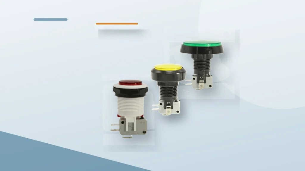
Normally open vs normally closed push button should be selected by matching the electrical function, mechanical interface, environment, and verification plan—not by copying a generic diagram or choosing from appearance alone. Normally open and normally closed describe the electrical state when the button is not actuated. They do not describe momentary versus maintained action. The safest choice depends on the control objective, fault response, monitoring logic, and the requirements of the finished machine. This guide gives engineers and OEM buyers a practical way to define the requirement, compare samples, and avoid a part that works on the bench but fails after installation. Application-focused view using the matching LEMA product. What the term means in this application Normally open and normally closed describe the electrical state when the button is not actuated. They do not describe momentary versus maintained action. The safest choice depends on the control objective, fault response, monitoring logic, and the requirements of the finished machine. The first job is to separate the switch's name from its required behavior. Product names are often shortened for search or purchasing, while an engineering drawing defines the contact state, terminal numbering, operating point, allowable travel, mounting reference, and ratings. If those details are missing, two parts with similar names may behave differently. Write the control requirement as a short sequence: the condition before actuation, the physical action that causes actuation, the electrical state after actuation, and the condition that resets it. This sequence prevents confusion between mechanical action and contact logic. It also gives the controls engineer, mechanical designer, buyer, and supplier one shared description to review. Do not treat a catalog current rating as a universal permission to switch any...

Leggi di più
Foot Switch Pedal Force and Operator Ergonomics
Blog LEMA Electric

Foot Switch Pedal Force and Operator Ergonomics

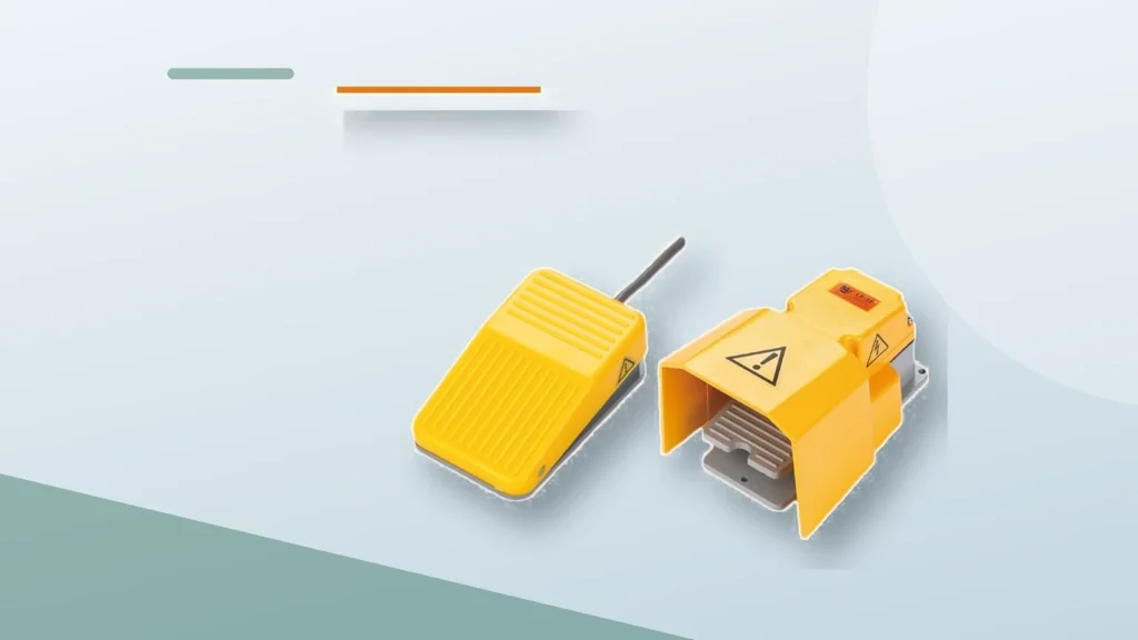
Foot switch pedal force should be selected by matching the electrical function, mechanical interface, environment, and verification plan—not by copying a generic diagram or choosing from appearance alone. Pedal force affects accidental activation, fatigue, stability, and repeatability. There is no universal best force: the correct value depends on footwear, seated or standing posture, work pace, guard design, travel, and the consequence of an unintended command. Evaluation should use representative operators and the real floor position. This guide gives engineers and OEM buyers a practical way to define the requirement, compare samples, and avoid a part that works on the bench but fails after installation. Application-focused view using the matching LEMA product. What the term means in this application Pedal force affects accidental activation, fatigue, stability, and repeatability. There is no universal best force: the correct value depends on footwear, seated or standing posture, work pace, guard design, travel, and the consequence of an unintended command. Evaluation should use representative operators and the real floor position. The first job is to separate the switch's name from its required behavior. Product names are often shortened for search or purchasing, while an engineering drawing defines the contact state, terminal numbering, operating point, allowable travel, mounting reference, and ratings. If those details are missing, two parts with similar names may behave differently. Write the control requirement as a short sequence: the condition before actuation, the physical action that causes actuation, the electrical state after actuation, and the condition that resets it. This sequence prevents confusion between mechanical action and contact logic. It also gives the controls engineer, mechanical designer, buyer, and supplier one shared description to review. Do not treat a catalog current rating...

Leggi di più
2-Pin Toggle Switch Wiring and Applications
Blog LEMA Electric

2-Pin Toggle Switch Wiring and Applications

2 pin toggle switch should be selected by matching the electrical function, mechanical interface, environment, and verification plan—not by copying a generic diagram or choosing from appearance alone. A two-pin toggle switch is normally a simple series on/off device, but pin count alone does not prove function. The installer must identify the contact arrangement from the drawing or continuity test, keep the switch within its load rating, and use a relay when the controlled load exceeds the switch's suitable duty. This guide gives engineers and OEM buyers a practical way to define the requirement, compare samples, and avoid a part that works on the bench but fails after installation. Application-focused view using the matching LEMA product. What the term means in this application A two-pin toggle switch is normally a simple series on/off device, but pin count alone does not prove function. The installer must identify the contact arrangement from the drawing or continuity test, keep the switch within its load rating, and use a relay when the controlled load exceeds the switch's suitable duty. The first job is to separate the switch's name from its required behavior. Product names are often shortened for search or purchasing, while an engineering drawing defines the contact state, terminal numbering, operating point, allowable travel, mounting reference, and ratings. If those details are missing, two parts with similar names may behave differently. Write the control requirement as a short sequence: the condition before actuation, the physical action that causes actuation, the electrical state after actuation, and the condition that resets it. This sequence prevents confusion between mechanical action and contact logic. It also gives the controls engineer, mechanical designer, buyer, and supplier one shared...

Leggi di più
UL Limit Switch Requirements for OEM Equipment
Blog LEMA Electric

UL Limit Switch Requirements for OEM Equipment

Ul limit switch should be selected by matching the electrical function, mechanical interface, environment, and verification plan—not by copying a generic diagram or choosing from appearance alone. A UL mark is not a generic quality label and it cannot be inferred from appearance. The exact switch model, rating, environmental category, and conditions of acceptability must match the finished equipment evaluation. Buyers should request the certification record and compare model identifiers rather than asking only whether a supplier is 'UL approved.' This guide gives engineers and OEM buyers a practical way to define the requirement, compare samples, and avoid a part that works on the bench but fails after installation. Application-focused view using the matching LEMA product. What the term means in this application A UL mark is not a generic quality label and it cannot be inferred from appearance. The exact switch model, rating, environmental category, and conditions of acceptability must match the finished equipment evaluation. Buyers should request the certification record and compare model identifiers rather than asking only whether a supplier is 'UL approved.' The first job is to separate the switch's name from its required behavior. Product names are often shortened for search or purchasing, while an engineering drawing defines the contact state, terminal numbering, operating point, allowable travel, mounting reference, and ratings. If those details are missing, two parts with similar names may behave differently. Write the control requirement as a short sequence: the condition before actuation, the physical action that causes actuation, the electrical state after actuation, and the condition that resets it. This sequence prevents confusion between mechanical action and contact logic. It also gives the controls engineer, mechanical designer, buyer, and supplier one...

Leggi di più
Micro Switch Operating Force: How to Match Force and Travel
Blog LEMA Electric

Micro Switch Operating Force: How to Match Force and Travel

Micro switch operating force should be selected by matching the electrical function, mechanical interface, environment, and verification plan—not by copying a generic diagram or choosing from appearance alone. Operating force is the force needed to move the actuator to its operating point. It must be considered together with release force, pretravel, overtravel, actuator geometry, temperature, and manufacturing tolerance. A mechanism that only just reaches the nominal operating point can become intermittent as parts wear or dimensions stack up. This guide gives engineers and OEM buyers a practical way to define the requirement, compare samples, and avoid a part that works on the bench but fails after installation. Application-focused view using the matching LEMA product. What the term means in this application Operating force is the force needed to move the actuator to its operating point. It must be considered together with release force, pretravel, overtravel, actuator geometry, temperature, and manufacturing tolerance. A mechanism that only just reaches the nominal operating point can become intermittent as parts wear or dimensions stack up. The first job is to separate the switch's name from its required behavior. Product names are often shortened for search or purchasing, while an engineering drawing defines the contact state, terminal numbering, operating point, allowable travel, mounting reference, and ratings. If those details are missing, two parts with similar names may behave differently. Write the control requirement as a short sequence: the condition before actuation, the physical action that causes actuation, the electrical state after actuation, and the condition that resets it. This sequence prevents confusion between mechanical action and contact logic. It also gives the controls engineer, mechanical designer, buyer, and supplier one shared description to review. Do...

Leggi di più
Quadro elettrico di comando con spia luminosa: guida alla scelta degli interruttori OEM | LEMA
Blog LEMA Electric

Quadro elettrico di comando con spia luminosa: guida alla scelta degli interruttori OEM | LEMA

electrical control box with indicator light oem became a priority because Google Search Console already shows real impressions for this topic on LEMA. That signal indicates an existing audience, but the previous site coverage did not fully match the question. This guide turns the query into a practical selection, integration and purchasing workflow for equipment designers, panel builders, maintenance teams and industrial buyers. An electrical control box with indicator lights combines command devices, visual status, enclosure protection, internal wiring and documentation. For an OEM build, begin with an operating narrative: every push button position, selector state and lamp condition must map to a defined machine state. Then specify lamp voltage, colour, legend, brightness, test function and behavior after loss of power. Keep indication honest—a green lamp should not imply that a hazardous condition is safe unless the control architecture proves it. The RFQ should include enclosure size and material, cutout drawings, wire labels, terminal blocks, incoming power, schematics, inspection records and applicable market requirements. Application view showing practical integration points for electrical control box with indicator light oem. What electrical control box with indicator light oem means in a real design A useful specification begins with behavior, not a catalogue photo. Write down what moves, what the operator or machine is trying to achieve, when the electrical state must change, and what should happen if a conductor opens or the device fails to reset. Separate the field device from the controller logic: a switch reports or commands a state, while the relay, PLC or control circuit decides how the machine responds. Similar product families often contain several contact arrangements, actuator styles, terminal forms and mounting versions. The family name helps...

Leggi di più
Spring Pin Plunger Limit Switch Selection and Mounting Guide
Blog LEMA Electric

Spring Pin Plunger Limit Switch Selection and Mounting Guide

spring pin plunger limit switch became a priority because Google Search Console already shows real impressions for this topic on LEMA. That signal indicates an existing audience, but the previous site coverage did not fully match the question. This guide turns the query into a practical selection, integration and purchasing workflow for equipment designers, panel builders, maintenance teams and industrial buyers. A spring pin plunger limit switch is best for controlled, nearly axial contact. The machine target depresses the plunger until the internal contact changes state; the return spring resets the mechanism when the target leaves. A rigid direct plunger provides accurate position sensing but tolerates less lateral scraping than a roller or flexible actuator. The designer must control approach direction, target hardness and finish, operating travel, overtravel, release clearance and impact speed. If the target can arrive from an angle, redesign the cam surface or choose a roller-style actuator instead of forcing the pin sideways. Application view showing practical integration points for spring pin plunger limit switch. What spring pin plunger limit switch means in a real design A useful specification begins with behavior, not a catalogue photo. Write down what moves, what the operator or machine is trying to achieve, when the electrical state must change, and what should happen if a conductor opens or the device fails to reset. Separate the field device from the controller logic: a switch reports or commands a state, while the relay, PLC or control circuit decides how the machine responds. Similar product families often contain several contact arrangements, actuator styles, terminal forms and mounting versions. The family name helps discovery but does not define a production part. Use the complete model...

Leggi di più
Simbolo dell'interruttore SPDT, logica dei terminali e guida agli schemi
Blog LEMA Electric

Simbolo dell'interruttore SPDT, logica dei terminali e guida agli schemi

Il simbolo dell’interruttore SPDT è diventato una priorità perché Google Search Console mostra già impressioni reali relative a questo argomento su LEMA. Questo segnale indica l’esistenza di un pubblico, ma la precedente copertura del sito non corrispondeva pienamente alla domanda. Questa guida trasforma la ricerca in un flusso di lavoro pratico di selezione, integrazione e acquisto per progettisti di apparecchiature, costruttori di quadri elettrici, squadre di manutenzione e acquirenti industriali. Il simbolo dell’interruttore SPDT mostra un contatto comune mobile che può collegarsi a uno qualsiasi dei due contatti fissi. Descrive la logica elettrica, non l’aspetto fisico di un interruttore reale. Uno schema può mostrare lo stato normale o diseccitato a seconda delle convenzioni di disegno, mentre la parte posteriore di un prodotto può rispecchiare ciò che suggerisce una visione frontale. Etichettare i fili con COM, NO e NC — oppure comune, polo A e polo B — solo dopo aver verificato lo schema del produttore e la continuità. L’interruttore SPDT può selezionare segnali, invertire la logica, fornire uscite alternative o creare una coppia NO/NC per l’ingresso di un controller. Vista applicativa che mostra i punti di integrazione pratici per il simbolo dell’interruttore SPDT. Cosa significa il simbolo dell’interruttore SPDT in un progetto reale Una specifica utile parte dal comportamento, non da una foto di catalogo. Annotate cosa si muove, cosa l’operatore o la macchina sta cercando di ottenere, quando lo stato elettrico deve cambiare e cosa dovrebbe accadere se un conduttore si apre o il dispositivo non riesce a ripristinarsi. Separate il dispositivo di campo dalla logica del controllore: un interruttore segnala o comanda uno stato, mentre il relè, il PLC o il circuito di controllo decide come la macchina risponde. Le famiglie di prodotti simili contengono spesso diverse configurazioni dei contatti, tipi di attuatori, forme dei terminali e versioni di montaggio. Il nome della famiglia aiuta a individuare il prodotto, ma non definisce un componente di produzione. Utilizzate il suffisso completo del modello, il disegno con controllo delle revisioni e lo schema dei terminali....

Leggi di più