
A screw-terminal toggle is only as reliable as the drawing and process around it. Put the conductor, termination style, rear access, inspection method and service label into one controlled package before a buyer approves samples.
Important: a familiar screw head does not establish torque, current capacity, environmental suitability or approval. Those limits must come from the selected-model documentation. Source note: IEC 61058-1 publication scope and selected-model documentation.
– FAQs
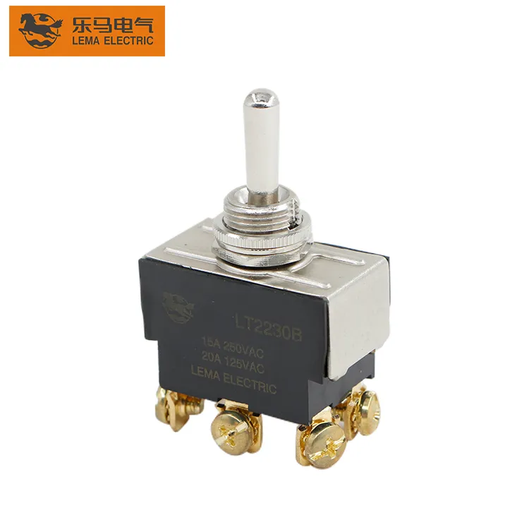
Part 1. What changes when an OEM specifies screw terminals?
Screw terminals move the decision beyond circuit form. The engineering file must state the conductor construction, whether an end treatment is required, access for the tool, the rear-space envelope, and how the operator or inspector knows the connection is complete. This prevents purchasing from choosing by photo or terminal count alone.
| Decision field | Record in the package | Send with quote |
|---|---|---|
| Duty | Voltage, load type, steady current and inrush | Yes |
| Harness | Conductor, insulation, routing and termination method | Yes |
| Panel | Cutout, thickness and rear access | Yes |
| Service | Label, inspection point and replacement rule | Yes |
Start at the LEMA Toggle Switch product line after the application file exists.
Part 2. Which conductor and terminal inputs belong in the drawing?
Use the exact drawing revision for terminal positions, then identify the wire and the route that reaches each connection. Keep the load path beside the terminal designation so the assembly team does not infer it from color alone. A connector, ferrule, lug or bare-conductor instruction should be a released process choice, not an assumption copied from an older panel.
When the circuit is single-pole double-throw, the SPDT terminal identification guide helps keep common and throw labels aligned with the harness.
Part 3. How should access and clearance be planned?
Measure the tool path, wire bend, strain-relief path, adjacent hardware and the removable-panel sequence together. A terminal that is reachable on a loose sample may be inaccessible after a boot, label, rear cover or neighboring component is installed. Show the required approach direction on the mounting drawing and reserve service room for future replacement.
- Keep conductor bend space behind the panel.
- Separate tool access from the lever operating envelope.
- Prevent sharp edges from controlling the wire route.
- Use the panel cutout and rear-clearance guide for mounting-envelope detail.
Part 4. Which assembly and inspection controls prevent rework?
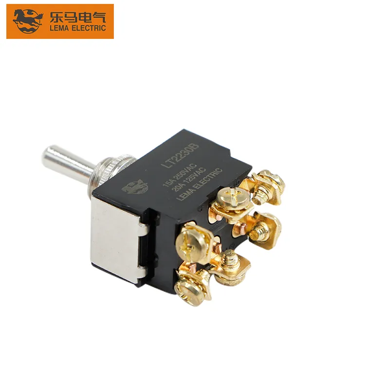
Define a visible sequence: identify terminal, prepare conductor, terminate by the approved work instruction, inspect, then perform the electrical check. The inspection record should identify the drawing revision and the terminal map. That traceability matters when a harness is reworked after a panel layout change.
Do not turn a generic “tighten terminal” note into an undocumented value. The selected-model documentation and controlled factory process determine the applicable method and limit.
Part 5. How should service and change control be documented?
Service teams need more than a generic description such as “toggle switch.” Put circuit form, terminal map, drawing revision and replacement boundary on the service record. If a new supplier, wire, coating or panel thickness is introduced, route it through the same review instead of assuming the screw terminal makes the change harmless.
For two independent paths, retain a pole-by-pole record using the DPDT selection checklist. For higher-load applications, keep load and terminal review together rather than relying on an appearance label.
Part 6. What should be validated before a harness release?
Build a production-intent panel, verify terminal assignment against the schematic, check the finished harness can be accessed and inspected, and confirm the operator sequence does not create an unintended path. Record any model-specific documentation needed before approving a sample.
Fit Boundary: this article structures harness, access and inspection planning. It does not certify torque, current rating, environmental sealing, approval or lifetime for any model.
Part 7. How can LEMA support a screw-terminal inquiry?
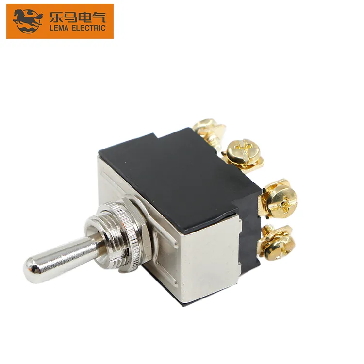
Use the LT1 series toggle switch page as a public starting point after the circuit and mounting package is ready.
Send with the inquiry:
- Circuit and terminal map
- Duty, inrush and harness description
- Panel cutout, rear clearance and service-access notes
- Volume, sample timing and requested documentation
Send a toggle-switch RFQ with the controlled drawing package.
## FAQ
What information belongs in a screw-terminal toggle RFQ?
Include circuit form, terminal map, duty, conductor and termination plan, panel clearance, volume and sample timing.
Can terminal torque be assumed from a similar switch?
No. Use the selected-model documentation and approved process; similar appearance is not evidence.
Does a screw terminal remove the need for strain relief?
No. Routing and strain relief remain harness and enclosure decisions.
How should service teams avoid terminal swaps?
Use the released circuit form, terminal labels and drawing revision instead of a generic replacement description.
When should a buyer select a different terminal style?
When the documented assembly process, access or service needs cannot be met by the selected terminal arrangement.
What must be validated before production release?
Validate terminal assignment, access, inspection, harness routing and model-documentation requirements on a production-intent panel.
## References