
A 12V Push Button Switch: Low-Voltage Control Circuit Guide starts with one idea: the button is an operator contact on a low-voltage rail, not a universal power switch for every load. This article maps action type, NO/NC behaviour, control-versus-power staging, flyback protection, and logic isolation, then points to PBS Series ordering options when the front-panel part must match that plan.
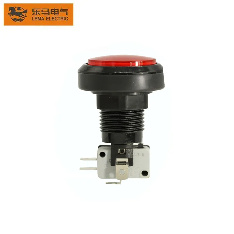
This figure shows a red PBS-series operator head used on low-voltage panels.
What a 12V push button actually controls
Electrically, a 12V push button switch only opens or closes contacts when an operator presses the actuator. In plain language, it is a human-operated gate on a control circuit, not a guarantee that the connected device can be powered through those contacts alone.
On OEM panels, that distinction matters early. A jog button on a conveyor console may only need to pulse a control input, while a lamp test may share the same rail but a different contact job.
Treat the button as a deliberate interface choice. Document which circuit it is allowed to interrupt, which rail it sits on, and what happens the moment the operator releases or presses again.
Momentary vs maintained on a 12V control rail
Momentary action keeps the changed contact state only while the button is held. Maintained / latching keeps the new state after release until the next deliberate actuation. The wrong choice turns a safe jog into an unintended continuous run, or forces an operator to hold a button that should stay latched.
Use this scan table when the panel drawing is still flexible.
| Operator job on the 12V rail | Prefer | Why it fits |
|---|---|---|
| Jog, inch, horn, reset pulse, start command into a PLC | Momentary | Circuit returns when the hand leaves |
| Local enable that must stay on without holding | Maintained / latching | State persists after release |
| Temporary override that must fail safe when released | Momentary | Release restores the resting path |
| Mode that operators expect to “click and leave” | Maintained / latching | Matches on-off mental model |
Procurement language often says “on off push button” when the real need is latching, and “start button” when the real need is momentary. Lock the action type in the BOM note before colour or LED debates begin. Secondary phrases such as momentary vs latching push button belong in that note so purchasing and wiring stay aligned.
NO, NC, and the common terminal
Normally Open (NO) contacts rest open and close when pressed — push-to-make. Normally Closed (NC) contacts rest closed and open when pressed — push-to-break. The Common (C) terminal is the shared pole that the NO or NC path returns through.
If the machine should energize a path only while pressed, NO is usually the direct match. If the resting machine state depends on a closed path that must break on press, NC is the match. Community builds repeatedly fail when someone owns an NC hardware part but expects press-to-supply behaviour without an inversion stage.
| Contact label | Resting circuit | While pressed | Typical 12V control use |
|---|---|---|---|
| NO | Open | Closed | Press-to-start, press-to-horn, press-to-command |
| NC | Closed | Open | Press-to-break a path that is normally live |
| C / COM | Shared pole | Shared pole | Ties the selected NO or NC path into the rail |
Confirm labels on the specific switch drawing before harness cut. Guessing from pin count alone is how press-to-energize jobs get wired as press-to-kill.
Control path vs power path
A healthy 12V push button switch wiring plan separates the operator contact from the heavy current path whenever the load outgrows what those contacts should carry. The button then commands a relay / driver stage, and that stage switches the motor, heater, solenoid bank, or lamp string.
Imagine a packaging cell where the front-panel start button sits on a clean control rail. The relay coil listens to that rail; the relay contacts feed the actuator. The operator still feels a direct press, but the contact set is no longer asked to be the power switch for the whole machine.
Ask one blunt question before you freeze the schematic: should releasing the button only stop a command, or must the button itself interrupt the full load current? If the second answer is “yes” only because the drawing is old, redesign toward a sized power stage.
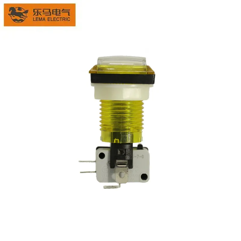
This figure shows the actuator body and microswitch terminals used in control wiring.
Inductive loads and flyback diodes
Relays and solenoids store energy in their coils. When a DC path opens, that energy tries to keep current flowing and creates a voltage spike. A reverse-biased flyback / freewheel diode across the coil gives that energy a safe path so the spike does not hammer the driving contact or transistor.
Important: Field builders who switch a 12V inductive load without a freewheel diode report contact arcing, welded contacts, and noisy resets on nearby controllers — source: Arduino Forum thread on flyback diodes.
Treat coil suppression as part of the circuit, not an optional accessory.
A 12V relay control circuit commanded by a push button still needs that diode on the coil even when the button itself looks small and harmless. Place the diode as close to the coil terminals as practical, cathode toward the positive coil supply for the usual low-side switched arrangement.
Do not confuse coil suppression with load-side filtering for motors or heaters. Those may need their own measures; the diode rule here is specifically about inductive coils on DC control rails.
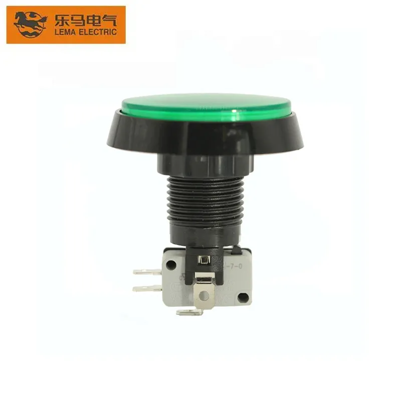
This figure shows another PBS colourway used on OEM front panels.
When the button must talk to a controller
A 12V operator rail and a microcontroller or logic input are different electrical neighbourhoods. Feeding the button’s 12V signal straight into a logic pin is a common way to destroy the input. Prefer an optocoupler / level translation stage so the press becomes a safe logic event.
Optocouplers keep the domains isolated when noise or ground shifts are likely. Level translation without isolation can work on clean benches, but OEM panels with long cable runs usually deserve the isolation habit.
If the controller already expects dry contacts at its own rated input, wire the push-button contacts as a dry contact into that input circuit instead of sharing the raw 12V lamp rail. Match the controller manufacturer’s input type before inventing a hybrid.
Keep LED indicator wiring on its own understood path when the head is illuminated. An LED indicator option can share the control idea of the button without sharing the logic pin.
A practical checklist before you order
Freeze these decisions in writing before colour chips and catalogue browsing take over:
- Action type: momentary or maintained / latching
- Contact behaviour: NO, NC, or both, plus how Common is used
- Electrical role: dry control contact versus direct load interrupt
- Power staging: whether a relay / driver stage carries the load
- Inductive protection: flyback / freewheel diode on every relevant DC coil
- Logic interface: optocoupler / level translation or dry contact into a rated input
- Operator cues: whether an LED indicator option is required
- Family options: whether a KW7 micro switch attachment is needed on the chosen head
Cross-check adjacent intents so this page stays in its lane. Emergency-stop hardware planning belongs on the dedicated emergency stop push button OEM guide. Illumination-first panel decisions belong on the illuminated push button switch OEM guide.
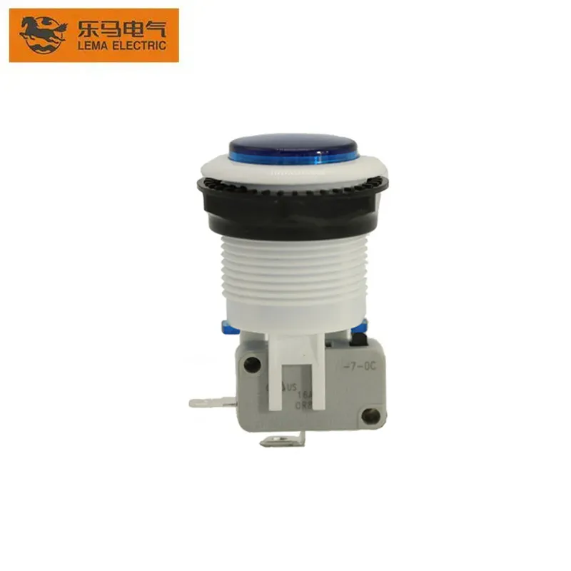
This figure shows a translucent head style often paired with an LED indicator option.
Selecting PBS Series for the panel front
Once the control architecture is settled, the front-panel part is a fitment decision rather than a rescue plan. The PBS Series Push Button Switch is LEMA’s push-button family for industrial and commercial operator interfaces, including game-machine and automation-style panels described on the product page.
Ordering language on that page includes colour codes R, Y, B, G, P, and W, plus LED light options written as with LED (L) or without LED. Some PBS models can be equipped with a KW7 micro switch; that option must not be assumed for every head in the family.
Choose PBS when you need a clear colour/LED front-of-panel language after the 12V control path is already designed. Do not choose it as a substitute for a verified emergency-stop device, and do not invent IP, certification, amp, or cutout claims that are not confirmed for the exact model you are buying.
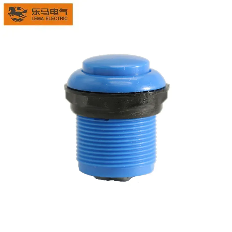
This figure is the product recommendation view for the PBS series family.
Open the product page, match the colour and LED fields to the panel drawing, and confirm whether the selected model needs the KW7 attachment path before the harness is cut.
FAQ
Should a 12V push button carry the full load current?
Often no. Use the button as a control contact that commands a sized relay or driver when the load is heavier than those contacts should interrupt. Small indicator loads can be different, but treat direct load switching as a deliberate, rated decision rather than a default.
Momentary or latching for a 12V control panel?
Pick momentary when the circuit should return the moment the operator releases. Pick latching when the state must remain until the next press. Write that choice into the BOM so purchasing does not substitute an on-off part for a jog part.
Do I need NO or NC to energize a path when pressed?
Press-to-energize usually wants a normally open path, or an intentional inversion if only NC hardware is available. Confirm resting versus pressed states on the drawing before the harness is built.
Why put a diode across a 12V relay or solenoid coil?
The coil stores energy; opening the DC path without a freewheel path can spike voltage, arc contacts, or upset nearby electronics. A correctly oriented flyback diode is the standard fix for that coil.
Can I wire a 12V button straight into a microcontroller pin?
No. Keep the 12V domain off the logic pin. Use isolation, level translation, or a controller input that is explicitly rated for the contact arrangement you intend.
Does every PBS model include an LED or a KW7 micro switch?
No. LED is an ordering option written as with or without LED, and KW7 is available for some models only. Confirm both on the exact configuration you order.
Is the PBS series an IP-rated, certified, or emergency-stop device by default?
This guide does not assert IP ratings, certifications, electrical ratings, cutout sizes, or emergency-stop functions for PBS. Confirm those needs on the specific model path, and use the dedicated emergency-stop article when that is the real intent.