
foot pedal foot switch wiring diagram selection starts by defining the required machine or equipment function, then matching the electrical interface, mechanical mounting and environment to one exact component. This guide explains how to identify terminals, choose NO or NC behavior, route the cable, test continuity and commission the machine input safely. A foot pedal is only the field input. The control circuit, relay, PLC or machine controller determines what the pedal actually starts, stops or enables. Treat every terminal diagram, rating and dimension as model-specific, and validate the assembled system before production use.
What the term means in an equipment design
A foot pedal is only the field input. The control circuit, relay, PLC or machine controller determines what the pedal actually starts, stops or enables. This distinction matters because search results often mix replacement parts, hobby wiring examples, complete control assemblies and bare industrial components. An OEM design needs a controlled specification rather than a visual match. Record the intended function in plain language, the normal and actuated states, the equipment supply, the connected load or controller input, and the consequence of a disconnected wire.
The component should be considered together with its mating part, mounting structure, conductors, enclosure and controller logic. A correct component installed in an unsuitable cutout or connected to an incompatible load is still an incorrect system. When a seller offers several variants under one family name, request the variant drawing and do not transfer ratings or terminal positions from a neighboring model.
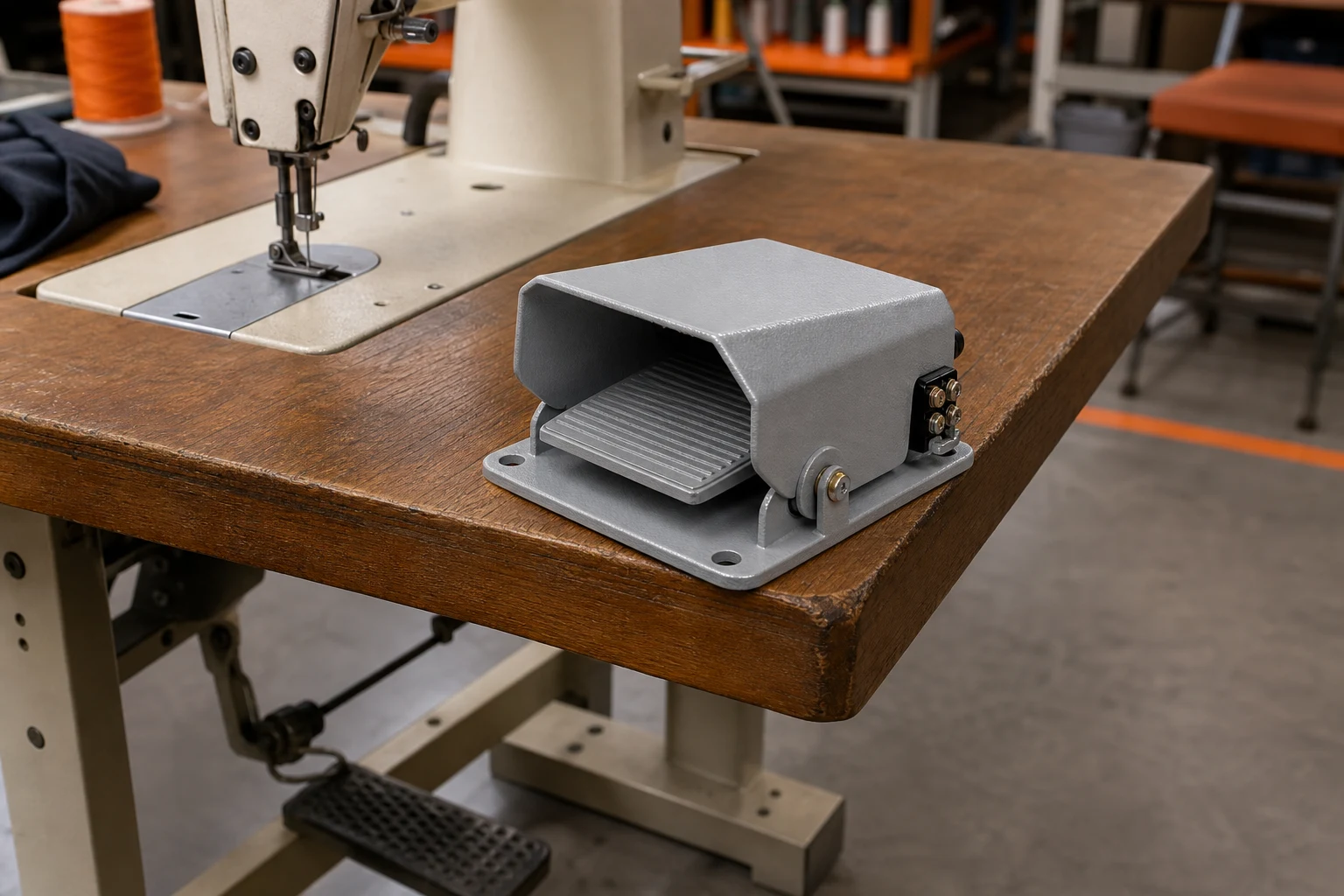
Selection decisions that prevent redesign
| Check | What to verify | Why it matters |
|---|---|---|
| Contact logic | COM, NO and NC identified from the device drawing | Prevents reversed machine behavior |
| Cable | Conductor count, insulation and strain relief match the circuit | Reduces loose connections and jacket damage |
| Continuity | State changes consistently through full pedal travel | Confirms the contact and mechanism work together |
| Machine response | Input changes safely before live production | Separates switch faults from controller logic |
The table is deliberately qualitative because the correct numerical limits come from the exact model datasheet and the equipment design. During comparison, reject any option whose drawing leaves a required field unspecified. A lower price or shorter lead time does not compensate for an unknown terminal material, ambiguous contact state, insufficient panel retention or an undocumented environmental boundary.
Define the electrical role before choosing hardware. A PLC input, relay coil, lamp, motor control circuit and direct resistive load impose different conditions. Switching current is not described by amperes alone: voltage, AC or DC, inrush, inductance, operating frequency and expected fault behavior all affect suitability. The NIST SI guidance for electric current explains the SI basis for current measurement, while the exact permissible load must come from the selected device documentation.
Mechanical integration and tolerance review
Build a tolerance chain from the target or mating connector through the component to the panel or bracket. Include hole position, cutout size, panel thickness, fastener access, actuator travel, cable bend radius and nearby service clearance. The nominal CAD position is not enough; evaluate the least favorable combination of component, panel and assembly tolerances. The mechanism should reach the intended state without using the component as a hard stop unless its documentation explicitly permits that use.
Check how production workers will orient and retain the part. Keying, flats, labels and asymmetric terminals should make an incorrect orientation difficult. Where orientation can be reversed, add a fixture check or an inspection feature. For field service, leave enough space to release a connector, remove a nut or test a terminal without disturbing unrelated wiring.
Electrical integration and safe work boundaries
Before wiring, isolate energy and confirm the circuit is de-energized using the site procedure. OSHA control of hazardous energy guidance describes the control of hazardous energy, and OSHA electrical safety guidance provides broader electrical-safety guidance. These sources establish safety context; they do not supply the component-specific pinout. Use the exact manufacturer diagram to identify each terminal, and use a meter only within the instrument, probe and worker qualification limits.
Prefer a harness and connector scheme that makes the intended connection obvious. Control conductor strip length, crimp tooling, pull-test sampling and insulation clearance. Provide strain relief so motion or service loads do not transfer directly to a terminal. If the component switches an inductive load, review suppression and contact protection with the control-system designer. Never infer conductor size, protective-device rating or grounding arrangement from an online example.

Installation sequence
- Confirm identity. Match the part number, revision, terminal diagram and mechanical drawing to the approved bill of materials.
- Inspect the mounting area. Remove burrs and debris; check panel thickness, hole spacing, flatness and access.
- Install without distortion. Seat the body, gasket, bracket or retention features evenly. Use documented hardware and torque where specified.
- Route and terminate conductors. Maintain bend radius, separation, strain relief and protection from sharp edges or moving parts.
- Perform an unpowered check. Verify continuity, state change, polarity or protective-earth path as applicable.
- Commission under controlled conditions. Observe the controller input and equipment response at slow or reduced-risk settings before normal operation.
Record any adjustment that affects the accepted result. A witness mark, measurement or controller diagnostic screenshot can make later troubleshooting much faster. If a part is adjustable, define who may adjust it and what acceptance window applies.
Commissioning and validation
Commissioning should separate component behavior from machine behavior. First prove the physical state and electrical output at the device. Then verify the input at the controller. Finally verify the commanded system response. This sequence prevents a software inversion, broken conductor or mechanical misalignment from being blamed on the component itself.
Test the full operating range, not one successful cycle. Include slow approach, normal approach, repeated operation, release/reset, cable movement and the least favorable permitted alignment. Where failure could create a hazard, the risk assessment must determine required architecture, diagnostics and protective functions. A general-purpose switch or socket must not be presented as a safety-rated function without appropriate evidence.
Common specification and installation mistakes
- Choosing from a product photo while ignoring the exact drawing and suffix.
- Confusing normal contact state with the state expected by the controller.
- Applying a headline current rating to a different voltage or load type.
- Omitting panel thickness, mating connector, cable exit or service clearance.
- Assuming one sealed part makes the complete enclosure suitable for the environment.
- Testing only the component and not the assembled machine response.
- Failing to document the approved sample, revision and acceptance criteria.
These mistakes are inexpensive to prevent during drawing review and expensive to correct after tooling, harness production or field installation. A short cross-functional review by mechanical, electrical, production and quality personnel usually exposes interface assumptions early.
OEM RFQ and supplier review checklist
Send suppliers an application package rather than only a keyword. State the function, expected state sequence, supply and load, mounting interface, environmental exposure, operating frequency, required service life, conductors or terminals, mating components, compliance market and planned validation. Ask the supplier to identify the exact proposed part number and return its controlled drawing with every deviation marked.
For samples, verify dimensions and operation against the returned drawing. Keep sample approval separate from production approval, because tooling, materials or subcomponents can change. Define incoming checks that can detect the most consequential errors without destructively testing every unit. If traceability matters, agree on date codes, lot records and change-notification expectations before purchase.
Related LEMA resources
Start with the foot pedal switch wiring product category to understand the available product family. Complement this guide with the related selection and sourcing guide, the installation or configuration article, and the OEM procurement reference. These pages address adjacent intents rather than duplicating the core topic here.
Video: a practical visual explanation
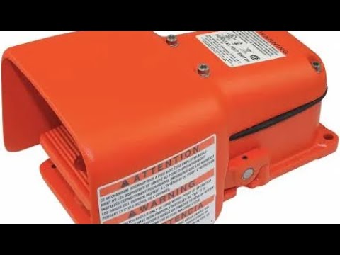
How to Rewire a Line Master Foot Switch by SolidToothSawmill provides a visual supplement. Use it to understand the physical concept, not as a substitute for the drawing and instructions of the exact component.
Frequently asked questions
What is the first thing to verify when selecting a foot pedal switch wiring?
Start with the required function and interface: what the operator or mechanism must do, what electrical state the controller expects, and how the exact component will mount and connect. Then compare the supplier drawing and rating information with the real application.
Can appearance alone identify the correct foot pedal switch wiring?
No. Similar-looking components can have different contact arrangements, terminal layouts, mounting dimensions, environmental protection and ratings. Use the exact part number, drawing and terminal markings.
Should installation be tested before production use?
Yes. Inspect the unpowered assembly, verify continuity or polarity as applicable, energize under controlled conditions, test every intended state, and document the accepted result before releasing the machine or product.
What information should an OEM RFQ include?
Include the application, circuit function, voltage and load type, mounting drawing, actuator or connector details, environment, cable or terminal requirement, expected quantity, compliance needs and validation plan.
Does this guide replace the equipment manufacturer’s instructions?
No. It is a selection and review framework. The exact component datasheet, equipment documentation, applicable standards and qualified electrical review control the final design.