LEMA NEWS CENTER

News & Blog

News Center

Planning a 24V Micro Switch for Control Circuits
Blog LEMA Electric

Planning a 24V Micro Switch for Control Circuits

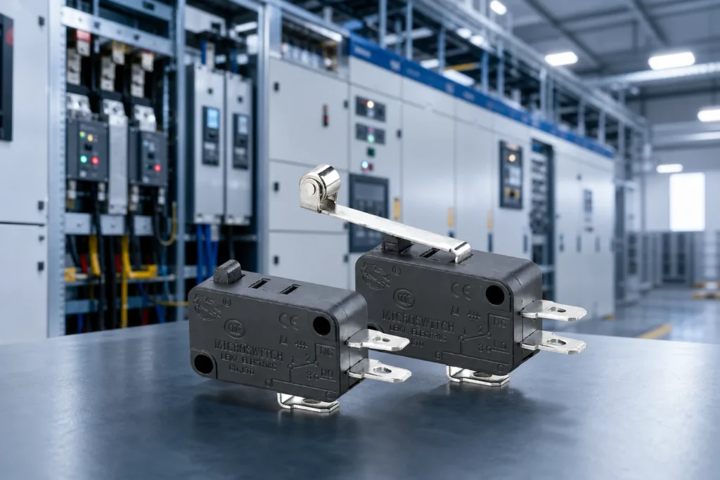
A 24V control circuit flips the usual switch worry upside down. Arcing nearly disappears, and with it the self-cleaning that keeps contacts fresh at mains voltage. The engineering questions become minimum load, surface films, and what the controller input really draws at the instant of closure. ContentsPart 1. What changes for a micro switch at 24V?Part 2. Why does minimum applicable load matter most?Part 3. How do controller inputs create hidden inrush?Part 4. Which wiring run effects need checking?Part 5. How should a 24V switch point be validated?Part 6. What belongs in the RFQ and Fit Boundary?Part 7. How can LEMA support a low voltage inquiry?FAQsReferencesPart 1. What changes for a micro switch at 24V? Control-voltage duty removes most arc erosion but also removes arc cleaning. A contact that only ever sees milliamps must conduct through whatever film forms during storage and standby. PropertyMains-level duty24V control dutyArc at openingSignificant, self-cleaningMinimal or absentDominant failureErosion and weldingFilm resistance and intermittencySelection focusRating and deratingMinimum load and material Families and options are indexed in the LEMA Micro Switch product line; the fields to read change, not the catalog. Part 2. Why does minimum applicable load matter most? Minimum applicable load states the smallest voltage and current at which the maker expects stable switching. Below it, resistance can wander enough to flip a logic input unpredictably. Voltage-specific habits from the 12V micro switch overview carry over; the 24V case simply tightens the same minimum-load discipline. Part 3. How do controller inputs create hidden inrush? Controller inputs are not resistors. Filter capacitors behind an input pin charge at contact closure, drawing a brief current spike that dwarfs the steady signal. Identify the input circuit type and...

Leer más
What Is a Limit Switch Used For? Industrial Applications and Selection Guide
Blog LEMA Electric

What Is a Limit Switch Used For? Industrial Applications and Selection Guide

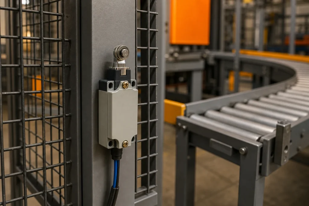
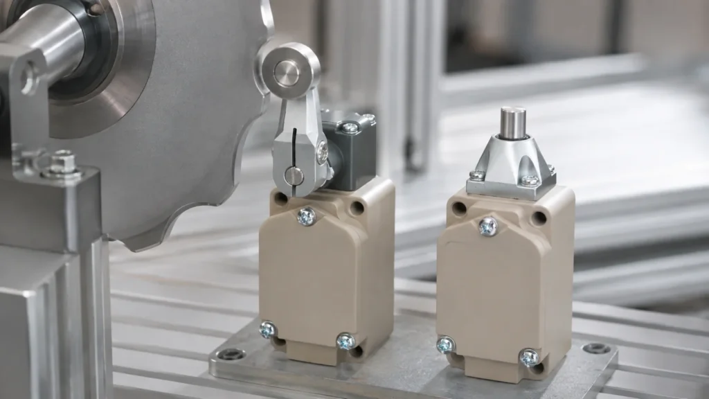
A limit switch is used to detect when a moving machine part reaches a defined position and to send a discrete electrical signal to a control circuit. Common uses include end-of-travel detection, door or guard position monitoring, conveyor item detection, indexing confirmation, valve position feedback and cycle sequencing. The device does not measure continuous distance; its actuator changes contact state after physical movement. Correct selection depends on the target motion, actuator geometry, operating and release points, overtravel, contact logic, electrical load, environment and mounting tolerance. A general-purpose limit switch must not be assumed to perform a safety function unless the complete safety system is designed and validated for that purpose.Plunger and roller actuator options suit different target motion. Where are limit switches used?On conveyors, a roller lever can confirm that a carrier or package has reached a transfer point. On machine tools, a plunger or roller can report that a slide is home or at a travel boundary. On doors and covers, the signal may tell a controller whether a movable element is closed. Valves, dampers and material-handling mechanisms use switches to confirm fully open, fully closed or intermediate positions. Packaging and assembly machines use them to verify that a mechanism completed one step before the next begins.The same physical event can serve different control purposes. A home signal establishes a reference, an end-of-travel signal prevents commanded motion beyond a working range, and a presence signal confirms that an object arrived. Write the purpose in plain language before choosing hardware because the required repeatability, response, failure behavior and controller logic are different. How does the switching mechanism work?The target contacts a plunger, lever, roller, rod or cam. Mechanical travel is...

Leer más
Selecting Micro Switches Near Heating Appliance Zones
Blog LEMA Electric

Selecting Micro Switches Near Heating Appliance Zones

Heating appliances rarely cook their switches at the headline cavity temperature. The component lives in a bracket zone warmed by conduction, convection, and duty cycling, and that local profile is the selection input. Measure it before shopping a maximum figure. ContentsPart 1. Why is the switch ambient different from the cavity figure?Part 2. How should the temperature profile be measured?Part 3. Which materials limit a switch at temperature?Part 4. How do temperature and electrical load interact?Part 5. Which mounting choices manage the heat path?Part 6. What belongs in the RFQ and Fit Boundary?Part 7. How can LEMA support a high temperature inquiry?FAQsReferencesPart 1. Why is the switch ambient different from the cavity figure? An oven cavity may run hot while the door switch position sits far cooler behind insulation, or a compact grill may soak its switch hotter than intuition suggests. Distance, insulation, and airflow decide, not the appliance's rated cooking figure. Heat pathMechanismDesign leverConductionBracket metal carries heat to the bodyIsolating spacers and bracket materialConvectionHot air pockets around the mountVent placement and orientationRadiationLine of sight to hot surfacesShields and gap design Families in the LEMA Micro Switch product line publish operating ranges per model, which only become useful once the local profile exists. Part 2. How should the temperature profile be measured? Instrument the actual switch position through the worst realistic cycle: preheat, full duty, and post-shutdown soak, when trapped heat often peaks. Log the profile rather than a single reading. The interlock example in the water heater interlock guide shows how one appliance documented its duty conditions; the same record works for any heat-adjacent point. Part 3. Which materials limit a switch at temperature? Housings, seals, and internal parts...

Leer más
Setting Adjustable Switch Travel on Conveyor Equipment
Blog LEMA Electric

Setting Adjustable Switch Travel on Conveyor Equipment

Set the trip point from the real conveyor mechanism, then document bracket adjustment, actuator path, tolerance stack, circuit input, and sample validation. This planning method does not promise anti-pinch, anti-jam, personnel protection, or conveyor performance. Use this article as an input checklist for an OEM discussion, not as a substitute for selected-model documentation or application testing. ContentsPart 1. What is adjustable travel setup?Part 2. Where should the trip position be measured?Part 3. How should the bracket adjustment be documented?Part 4. Which actuator-path checks matter?Part 5. How should the circuit input be reviewed?Part 6. What belongs in the RFQ and Fit Boundary?Part 7. How can LEMA support a conveyor inquiry?FAQsReferencesPart 1. What is adjustable travel setup? Start with the actual mechanism and the decision that the switch must support. Define the required state change, reference position, approach direction, and operating conditions before choosing a general product family. Input groupWhat to recordWhy it mattersFunctionRequired state and reference positionConnects the component to the installed taskMechanismTravel, force, and contact geometryDefines actuator reviewCircuitVoltage, load type, current, and inrushDefines electrical reviewEnvironmentExposure, service access, and mountingDefines validation conditions Use the LEMA Micro Switch product line as a live category route, then confirm the selected option against its model documentation. Part 2. Where should the trip position be measured? Use fixed drawing references rather than descriptions such as “near the end.” Record the nominal condition, tolerances, reset condition, and changes that require the setting to be reviewed again. For related mechanism choices, use the live mechanical actuator review article to frame the actuator and mounting discussion. Part 3. How should the bracket adjustment be documented? Describe the interface in enough detail that a sample can be installed in...

Leer más
Specifying an IP68 Micro Switch Sealing Envelope
Blog LEMA Electric

Specifying an IP68 Micro Switch Sealing Envelope

IP68 is a negotiated promise, not a fixed depth. The second digit 8 means continuous immersion under conditions the manufacturer and user agree, which makes your written envelope — depth, duration, chemistry, temperature — the real specification. Write it before comparing parts. ContentsPart 1. What does IP68 promise beyond IP67?Part 2. How should the immersion envelope be written?Part 3. Which entry points break sealed designs?Part 4. How do washdown chemistry and temperature interact?Part 5. Which validation steps prove the envelope?Part 6. What belongs in the RFQ and Fit Boundary?Part 7. How can LEMA support an IP68 inquiry?FAQsReferencesPart 1. What does IP68 promise beyond IP67? The first digit covers solids and the second covers water, and the jump from 7 to 8 changes the question. IPX7 describes temporary immersion under defined test conditions, while IPX8 hands the conditions to an agreement between maker and user. ClassWater conditionPractical readingIPX5 / IPX6Jets and heavy seasWashdown spray without immersionIPX7Temporary immersionDefined depth and time testIPX8Continuous immersionConditions agreed per application Sealed families in the LEMA Micro Switch product line state their construction approach; the envelope you write decides which applies. Part 2. How should the immersion envelope be written? Envelope writing means numbers: maximum depth, longest continuous immersion, total immersed hours per year, and whether the switch operates while submerged or only survives submersion. Each of those changes the sealing design. General sealing principles behind these choices are collected in the waterproof switch principles overview. Part 3. Which entry points break sealed designs? Water finds the interfaces, not the housing walls. The three recurring leak paths are the cable exit, the actuator penetration, and the mounting face. Specify the cable exit as a sealed system, including...

Leer más
Planning a Sealed Limit Switch Assembly for Wet Duty
Blog LEMA Electric

Planning a Sealed Limit Switch Assembly for Wet Duty

Define the target environment, enclosure interfaces, cable entry, actuator motion, and validation method as one installed system. An IP68 target cannot be assigned to a LEMA model from a category page; the complete assembly needs model-level review and testing. Use this article as an input checklist for an OEM discussion, not as a substitute for selected-model documentation or application testing. ContentsPart 1. What should an IP68 target describe?Part 2. Which enclosure interfaces belong in the plan?Part 3. How should cable entry be specified?Part 4. Why does actuator motion affect the system?Part 5. Which exposure conditions need validation?Part 6. What belongs in the RFQ and Fit Boundary?Part 7. How can LEMA support an enclosure inquiry?FAQsReferencesPart 1. What should an IP68 target describe? Start with the actual mechanism and the decision that the switch must support. Define the required state change, reference position, approach direction, and operating conditions before choosing a general product family. Input groupWhat to recordWhy it mattersFunctionRequired state and reference positionConnects the component to the installed taskMechanismTravel, force, and contact geometryDefines actuator reviewCircuitVoltage, load type, current, and inrushDefines electrical reviewEnvironmentExposure, service access, and mountingDefines validation conditions Use the LEMA Micro Switch product line as a live category route, then confirm the selected option against its model documentation. Part 2. Which enclosure interfaces belong in the plan? Use fixed drawing references rather than descriptions such as “near the end.” Record the nominal condition, tolerances, reset condition, and changes that require the setting to be reviewed again. For related mechanism choices, use the live sealed cable selection guide article to frame the actuator and mounting discussion. Part 3. How should cable entry be specified? Describe the interface in enough detail that...

Leer más
Reading a 16A 250V Rating Against the Real Load
Blog LEMA Electric

Reading a 16A 250V Rating Against the Real Load

A 16A 250V marking is a rated point, not a blanket permission. The numbers hold under the load type, switching rate, and temperature the maker tested. Read the marking as the beginning of verification, then prove the real circuit against the model document. ContentsPart 1. What does a 16A 250V marking actually state?Part 2. Which load types stress the contact differently?Part 3. How should inrush and switching rate be verified?Part 4. Why does thermal rise need an installed test?Part 5. Which wiring details protect the rating?Part 6. What belongs in the RFQ and Fit Boundary?Part 7. How can LEMA support a rating inquiry?FAQsReferencesPart 1. What does a 16A 250V marking actually state? Ratings are condition statements. The same contact that carries a resistive current comfortably can erode quickly on an inductive or lamp load at the identical ampere value. Marking elementWhat it usually coversWhat it leaves open16A figureRated current under stated conditionsYour load type and duty250V figureRated switching voltage classActual circuit transientsMarking togetherA tested combinationInrush, rate, and ambient Pull the full condition set from the series documentation in the LEMA Micro Switch product line rather than stopping at the housing print. Part 2. Which load types stress the contact differently? Load character decides contact stress. Heaters draw close to their steady value, motors multiply it at start, and capacitive or lamp loads spike hardest of all in the first milliseconds. Panel-level context for these load classes appears in the industrial panel selection guide; the rating question here is the same one, asked at the contact. Part 3. How should inrush and switching rate be verified? Measure or calculate the inrush the contact actually breaks and makes. A clamp trace at...

Leer más
Selecting Position-Sensing Inputs for Crane Motions
Blog LEMA Electric

Selecting Position-Sensing Inputs for Crane Motions

Crane Limit Switch Types selection begins with the installed mechanism and the real control input. Record hook, trolley, or bridge position; trip direction; actuator approach; mounting tolerance; and control input before asking for a model review. This guide does not claim safety integrity or lifting-equipment compliance. It supports component-level position-sensing selection and requires system-level engineering validation. ContentsPart 1. Which crane motions need position sensing?Part 2. How do hook, trolley, and bridge sensing differ?Part 3. Which actuator and mounting inputs matter?Part 4. How should control logic and circuit duty be reviewed?Part 5. What should installation validation cover?Part 6. What belongs in the RFQ and Fit Boundary?Part 7. How can LEMA support a crane inquiry?FAQsReferencesPart 1. Which crane motions need position sensing? Start with the required position signal, not the product label. The application drawing should show the moving feature, the state to be reported, and the consequence of a missed or early signal. Use the LEMA Limit Switch product line as a category route, then compare the final candidate with its model documentation. Selection fieldInput to documentWhy it mattersPositionTarget point and toleranceDefines the required signal windowMechanismApproach, travel, clearance, and side loadControls actuation repeatabilityCircuitContact state, voltage, load, and interfaceFrames electrical reviewEnvironmentContamination, vibration, temperature, and service accessFrames validation conditions Part 2. How do hook, trolley, and bridge sensing differ? Translate the motion into measurable positions. Identify the normal approach direction, the operating window, the release path, and every tolerance that can move the trip point. A layout review should also record whether adjustment is available and who controls it during installation. For a roller-driven mechanism, the roller limit switch applications guide can help frame the actuator-path discussion. It does not replace the drawing...

Leer más
Choosing NC or NO Logic for a Microswitch Circuit
Blog LEMA Electric

Choosing NC or NO Logic for a Microswitch Circuit

Normally closed and normally open describe the circuit before the actuator moves, and that free state is a design decision. Choose it from what the system must do when a wire breaks or a bracket loosens, not from which terminal is easier to reach. ContentsPart 1. What do normally closed and normally open mean?Part 2. How does failure behavior drive the state choice?Part 3. When is normally open the right default?Part 4. When does normally closed earn its place?Part 5. How should the controller read each state?Part 6. What belongs in the RFQ and Fit Boundary?Part 7. How can LEMA support a contact state inquiry?FAQsReferencesPart 1. What do normally closed and normally open mean? On a changeover microswitch, COM connects to the NC terminal in the free position and transfers to NO at the operating point. The words describe the resting circuit, nothing more. StateFree positionOperated positionNormally open pathCircuit openCircuit closedNormally closed pathCircuit closedCircuit openChangeover useBoth paths availableStates swap together Series documentation in the LEMA Micro Switch product line states which arrangements each family offers, so confirm availability before the schematic freezes. Part 2. How does failure behavior drive the state choice? Ask what the controller should believe when the signal disappears. A broken conductor, an unplugged connector, and a failed contact all read the same as an open circuit. Wiring the function so that open means stop turns most of those faults into safe stops instead of silent failures. Interlock examples in the elevator door interlock guide apply exactly this reasoning to door travel. Part 3. When is normally open the right default? Normally open suits event detection without a hazard behind it: counting products on a line, confirming...

Leer más
Hoist Limit Switch Guide: Travel Detection, Over-Travel and Selection
Blog LEMA Electric

Hoist Limit Switch Guide: Travel Detection, Over-Travel and Selection

A hoist limit switch detects when lifting equipment approaches a defined travel boundary and sends a signal to the hoist control system. Upper travel limiting helps prevent the hook block or load-handling device from moving into an unsafe mechanical condition, but the switch alone does not guarantee a safe stop. The complete result depends on the sensing method, actuator setup, controller logic, contactor or drive response, brake condition, stopping distance, inspection and applicable crane or hoist requirements. Operational and final over-travel limits may have different roles. Selection must therefore begin with the hoist design and risk assessment, not with a switch image or a generic current rating.Different actuators require different approach geometry and travel allowance. Operational limit versus final over-travel protectionAn operational upper limit normally stops routine upward travel before the mechanism enters the final prohibited region. A separate final limit, where required by the equipment design or applicable rules, provides another layer if normal travel control fails or is bypassed. These functions should not be casually combined in one adjustable point. The design must define which motion is interrupted, how reset occurs, whether lowering remains available, and what inspection is required after a final limit operates.Stopping distance matters. The hook block continues moving during detection, control processing, contactor or drive response and brake application. Load, speed, reeving, brake condition and mechanical elasticity influence the final stopping position. Set the actuator with verified margin under the equipment manufacturer's procedure and test first at slow speed without relying on a person standing near the hazard. How does the switching mechanism work?The target contacts a plunger, lever, roller, rod or cam. Mechanical travel is transferred to an internal snap-action or switching mechanism,...

Leer más
Consolidating Micro Switch Variants Across Appliance Lines
Blog LEMA Electric

Consolidating Micro Switch Variants Across Appliance Lines

Appliance platforms collect micro switch variants the way drawers collect cables. Each program adds one more lever, force, or terminal option until purchasing manages dozens of near-duplicates. Consolidation starts with an inventory, not with a favorite part number. ContentsPart 1. Why do appliance platforms accumulate switch variants?Part 2. How should switch points be inventoried?Part 3. How do duty profiles define consolidation groups?Part 4. Which actuator and terminal standards help most?Part 5. How should validation cover a consolidation?Part 6. What belongs in the RFQ and Fit Boundary?Part 7. How can LEMA support a consolidation inquiry?FAQsReferencesPart 1. Why do appliance platforms accumulate switch variants? Variant growth is organic: separate design teams, separate launch dates, and separate suppliers each solve a local problem. Nobody chooses thirty part numbers; portfolios drift there. Growth driverTypical resultConsolidation leverPer-program sourcingSame duty, different brandsCommon series with option codesCopy-paste with editsSlightly different leversStandard actuator menuTerminal convenienceMixed solder and quick-connectHarness-level terminal standard Anchor the exercise in a documented catalog such as the LEMA Micro Switch product line, where option codes make overlap visible. Part 2. How should switch points be inventoried? List every point across washers, dryers, ovens, dishwashers, and small appliances in one table: function, contact state, load, travel, environment, and annual volume. The inventory is the deliverable; opinions about similarity come later. Two published examples show the level of detail worth capturing per point: the refrigerator door switch guide and the water heater interlock guide. Part 3. How do duty profiles define consolidation groups? Group by duty profile: signal-level sensing, lamp and indicator loads, motor and heater interlocks, and wet-area points. Products differ; duties repeat. Signal points share dry-circuit contact needs.Power interlocks share inrush and rating review.Wet or...

Leer más
Selecting a Door Position Switch for Lift Equipment
Blog LEMA Electric

Selecting a Door Position Switch for Lift Equipment

Door Limit Switch for Lifts selection begins with the installed mechanism and the real control input. Record door travel, target position, actuator direction, mounting tolerance, and controller contact logic before asking for a model review. This is component selection for position and travel detection only. It does not claim a lift locking device, regulatory compliance, or completed safety redundancy. ContentsPart 1. What does a door limit switch do in lift equipment?Part 2. How should door travel and target positions be defined?Part 3. Which actuator and mounting details matter?Part 4. How should contact logic and controller inputs be reviewed?Part 5. What should installation validation cover?Part 6. What belongs in the RFQ and Fit Boundary?Part 7. How can LEMA support a lift-door inquiry?FAQsReferencesPart 1. What does a door limit switch do in lift equipment? Start with the required position signal, not the product label. The application drawing should show the moving feature, the state to be reported, and the consequence of a missed or early signal. Use the LEMA Limit Switch product line as a category route, then compare the final candidate with its model documentation. Selection fieldInput to documentWhy it mattersPositionTarget point and toleranceDefines the required signal windowMechanismApproach, travel, clearance, and side loadControls actuation repeatabilityCircuitContact state, voltage, load, and interfaceFrames electrical reviewEnvironmentContamination, vibration, temperature, and service accessFrames validation conditions Part 2. How should door travel and target positions be defined? Translate the motion into measurable positions. Identify the normal approach direction, the operating window, the release path, and every tolerance that can move the trip point. A layout review should also record whether adjustment is available and who controls it during installation. For a roller-driven mechanism, the roller limit switch applications...

Leer más