
SPDT wiring fails when teams guess terminals from a lever photo. Lock the common and each throw on the schematic first, then assign harness pins. A clean panel still misbehaves when C and throw labels drift between drawing revisions.
Important: Treat SPDT terminal identity as a drawing-controlled field, not a shop-floor nickname. Confirm contact paths against selected-model documentation before harness release. Source note: IEC 61058-1 publication scope and selected-model documentation.
– FAQs
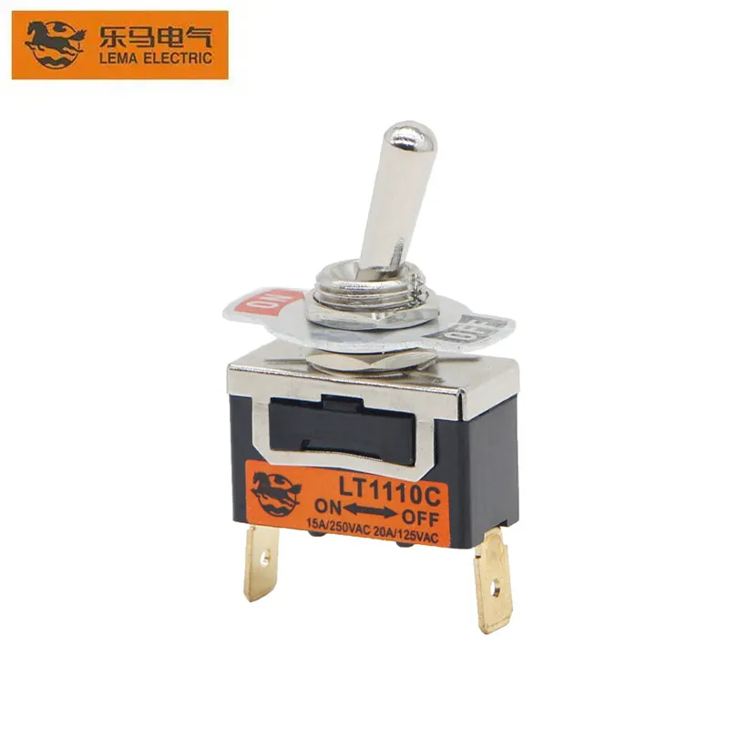
Part 1. Which terminals define an SPDT toggle on the drawing?
Start from the contact diagram: one common (C / COM) and two throws that the lever selects. Record which throw is ON in each maintained position and whether a center-off exists.
| Decision field | Input to document | Send with quote |
|---|---|---|
| Terminal map | C / throw labels on the drawing | Yes — labeled schematic |
| Circuit form | Maintained states the SPDT must express | Yes — printed form |
| Load path | Which throw carries which load | Yes — duty summary |
| Panel fit | Cutout, thickness, clearance | Yes — mounting envelope |
Browse the LEMA Toggle Switch product line only after the pin map exists.
Part 2. How should common and throw pins be labeled in the harness?
Harness labels should mirror the drawing characters exactly. If manufacturing uses color codes, keep a cross-reference table in the same package so service teams do not invent new names.
When the panel language still says ON-OFF without poles and throws, compare against the ON-OFF versus ON-OFF-ON logic guide before freezing SPDT hardware.
Part 3. When does SPDT wiring differ from simple ON-OFF slang?
Shop slang often collapses SPDT into “a three-screw toggle.” That shortcut hides which throw is live in each lever position and invites DPDT substitutions later.
Dual-circuit panels that truly need two poles should move to the DPDT dual-circuit selection checklist instead of forcing one SPDT to carry both paths.
Part 4. Which load and panel notes still belong beside the pin map?
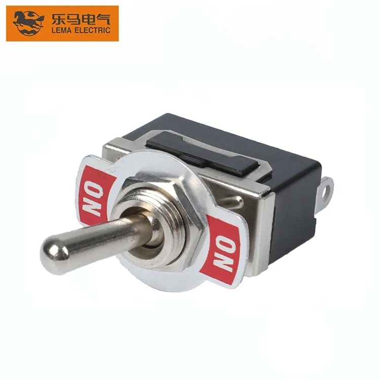
Pin identity does not replace electrical and mechanical review. Capture voltage class, steady current, inrush, terminal style, cutout, and rear clearance next to the SPDT map.
- Match solder versus screw terminals to the harness process.
- Keep inrush notes tied to the energized throw.
- Reject unmarked samples that lack a matching terminal drawing.
- Low-voltage accessory context remains useful via the 12V OEM panel toggle planning guide.
Part 5. How do OEMs prevent terminal swaps during service?
Service swaps create silent failures when BOM text only says “SPDT toggle.” Print terminal IDs on the schematic, nameplate callout, and spare-part label so purchasing cannot substitute by appearance.
| Control | Strong practice | Weak practice |
|---|---|---|
| BOM text | SPDT with drawing revision | Generic toggle SKU |
| Harness | Pins mapped to C / throws | Color-only notes |
| Spares | Same terminal drawing | Any three-terminal lookalike |
Part 6. How should SPDT wiring be validated before release?
Validate continuity on each throw, confirm the common lands where the harness expects, and cycle the lever against the operator script on a production-intent panel.
Fit Boundary: this guide covers drawing and harness identification only. Verify model-specific ratings, approvals, environmental sealing, and endurance against the applicable documentation before releasing hardware.
Part 7. How can LEMA support an SPDT wiring inquiry?
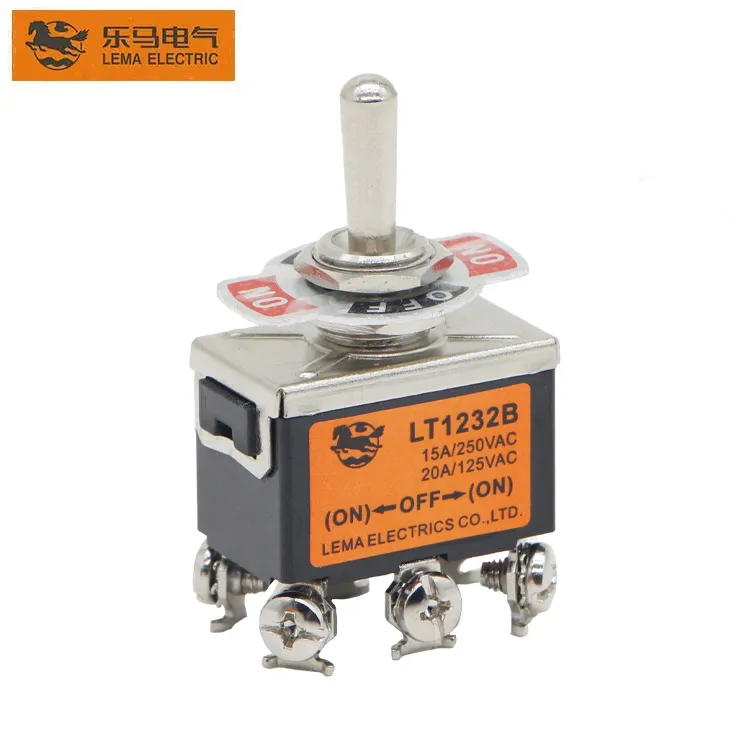
Use the LT1 series toggle switch page as a public starting point once the terminal map and mounting envelope are documented.
Send with the inquiry:
- SPDT terminal map with C / throw labels
- Voltage, steady current, load type, and inrush
- Cutout, panel thickness, and rear clearance
- Terminal style, volume, and sample timing
Product recommendation: request a documented LEMA review against the wiring drawing. Do not approve a part from an unlabeled photo.
Send a toggle-switch RFQ with the terminal map, duty, volume, and sample timing.
## FAQs
What does SPDT mean on a toggle switch?
SPDT means single-pole double-throw: one common terminal selects between two throw paths according to lever position.
How do I identify the common terminal?
Use the selected-model terminal drawing; do not assume center screw or a color mark without documentation.
Is every three-terminal toggle an SPDT?
No. Confirm poles, throws, and maintained states on the printed circuit form before wiring.
Can purchasing swap SPDT parts by appearance?
No. Lever look is not proof of terminal identity; the labeled drawing is the authority.
When should I choose DPDT instead of SPDT?
Choose DPDT when two independent poles must switch together; see the dual-circuit selection checklist rather than paralleling guesses on one SPDT.
What should an SPDT wiring RFQ include?
Include the terminal map, circuit form, load and inrush, cutout, terminal style, volume, and sample timing.
## References