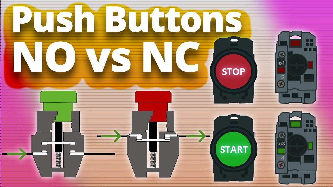
A push button switch symbol combines two separate ideas: the actuator that a person presses and the electrical contact state that changes. Read the contact in its normal, unactuated and de-energized condition unless the drawing states otherwise. A normally open contact is open at rest and closes when actuated; a normally closed contact is closed at rest and opens when actuated. An illuminated push button also has a lamp or LED circuit, which must be shown and wired separately from the contact circuit.
This guide explains how engineers, panel builders and buyers should interpret NO, NC, changeover, maintained, momentary and illuminated push-button symbols. It does not replace the symbol legend, applicable drawing standard or terminal diagram for the exact product.
Common push-button symbol meanings
| Drawing element | Meaning at normal state | Change when pressed | Typical verification |
|---|---|---|---|
| NO make contact | Current path is open | Contact closes | COM–NO continuity appears |
| NC break contact | Current path is closed | Contact opens | COM–NC continuity disappears |
| Changeover contact | COM is connected to NC | COM transfers to NO | Meter both paths in both states |
| Momentary actuator | Returns when released | Operates only while force is applied | Release test through full travel |
| Maintained actuator | Remains in selected state | Requires another action to reset | Operate and reset according to drawing |
| Lamp or LED | Independent indicator circuit | Illuminates when its supply is present | Check rated voltage and LED polarity |
Graphic details vary among IEC, ANSI and company-specific drawing systems. The project legend governs the drawing. The functional questions remain the same: what is the normal state, what mechanical action causes transfer, which terminals belong to each contact, and what returns the device to normal?
Start from the normal state
“Normal” usually means the device is installed, not pressed and not affected by an external operating force. It does not mean the machine is running normally. For a spring-return push button, this is normally the released position. For a maintained selector or latching push button, the drawing may define the state by position rather than by release, so the legend and operating narrative matter.
The IEC 60617 graphical-symbol preview includes manually operated switch and push-button concepts. Use the current applicable standard and your organization’s approved symbol library; do not redraw a symbol from an online image without confirming its convention.
Normally open and normally closed are contact states
A normally open push-button contact does not conduct in its defined normal state. Pressing the actuator moves the contact to the conducting state. It is often used for start, request or acknowledge signals, but the label “NO” does not guarantee a safe function or a particular terminal location.
A normally closed contact conducts at rest and opens when pressed. It can support stop or monitoring logic, yet a single NC contact is not automatically a safety-rated emergency-stop circuit. The system architecture, direct-opening behavior where required, fault detection, contact redundancy and controller all need separate evaluation.
Review the NO versus NC push-button guide for the operating distinction. On the drawing, annotate terminal numbers or wire references so the symbol can be traced to the physical contact block.
How to read a changeover contact
A changeover contact has a common terminal that transfers between two throws. In the normal state, COM connects to NC. When fully actuated, COM connects to NO. A schematic may show the moving contact angled toward its normal connection. Do not assume the center terminal is always COM: physical layouts vary, especially between solder-lug, screw-terminal and modular contact-block products.
For an isolated device, use a continuity meter to identify the connected pair at rest, then press the button through its full operating travel and identify the transferred pair. Record the result with terminal markings. If both paths appear closed, neither path transfers, or the reading changes with light vibration, stop and check the device, meter leads and actuator travel.
Momentary and maintained symbols
The contact symbol alone may not show whether the actuator returns automatically. A momentary push button uses spring return: it changes state while pressed and returns on release. A maintained or latching push button remains in the operated state until a second push, twist, pull or other defined reset action.
Drawings should show or note that mechanical behavior because it changes the machine sequence. A momentary start command can be latched in PLC logic or a relay circuit even though the physical button returns. Conversely, a maintained mechanical button may keep its contact state without software memory. Do not confuse electrical seal-in logic with a mechanically maintained actuator.
Illuminated push-button symbols contain two circuits
An illuminated push button combines contacts with a lamp or LED. The indicator circuit may share a housing but is electrically separate unless the exact product drawing shows an internal connection. Show the lamp with its own symbol and terminal references. For an LED, document the rated voltage, polarity and any built-in resistor or driver.
The indicator may be always on, on while pressed, or controlled from confirmed machine feedback. Those meanings are not interchangeable. A lamp driven directly from the push-button contact only proves the contact command exists; it may not prove the motor, valve or machine function actually changed state. For terminal identification principles, compare the four-pin push-button wiring guide.
Connect the schematic to terminal numbers
- Identify the device tag, such as PB1, and find every contact associated with it.
- Read the symbol in its defined normal state.
- Note each terminal number, wire number and contact-block designation.
- Separate contact terminals from lamp terminals.
- Confirm momentary or maintained action and the reset method.
- Compare the schematic with the manufacturer’s exact terminal drawing.
- Perform a de-energized continuity test before connecting the control circuit.
- Commission the final I/O state and indicator behavior under controlled conditions.
Cross-references matter when one operator actuates multiple contacts. The drawing may show those contacts in different locations for readability. A shared mechanical linkage should be indicated so the reader knows they operate together. The BOM must identify enough of the ordering code to reproduce that arrangement.
Symbol mistakes that create wiring errors
- Reading the drawing as if it shows the pressed state.
- Assuming NO and NC describe wire colors rather than contact states.
- Treating a lamp terminal as a contact terminal.
- Using a generic symbol without terminal or device references.
- Confusing a maintained actuator with a software-latched command.
- Assuming a red mushroom actuator proves an emergency-stop function.
- Mirroring a terminal layout when viewing the rear of the device.
A symbol is a functional statement, not a product certification. The current IEC 60947-5-1 control-circuit device standard includes electromechanical control devices such as push buttons and associated indicator equipment. The project engineer must identify the edition, regional requirements and scope actually required.
Review one control loop from drawing to hardware
Choose one push button and trace the complete loop before reviewing the rest of the panel. Start at the protected control supply, follow the conductor through the symbol, terminal references and intermediate devices, and finish at the PLC input or relay coil and its return. Confirm that the device tag on the drawing matches the physical label and BOM. Then operate the isolated button while checking continuity at the harness end. This catches reversed rear-view terminal layouts, wrong contact blocks and drawing revisions that no longer match the assembled panel.
After energization under an approved commissioning procedure, watch the controller input and indicator separately. The contact should change only in the state shown by the operating narrative. The lamp should represent the documented condition rather than merely proving that voltage exists somewhere in the enclosure. Record the observed rest, pressed, released and reset states. When a second contact is mechanically linked to the same actuator, test it at the same time and confirm that the drawing does not imply a sequence the product cannot guarantee.
Selection and RFQ checklist
Specify the required contact form, number of contact blocks, momentary or maintained action, operating and reset method, control voltage and current, load type, lamp technology and voltage, terminal style, panel cutout, mounting depth, ingress exposure, actuator shape, legend and applicable standard. Include the approved schematic symbol and terminal references in the drawing package.
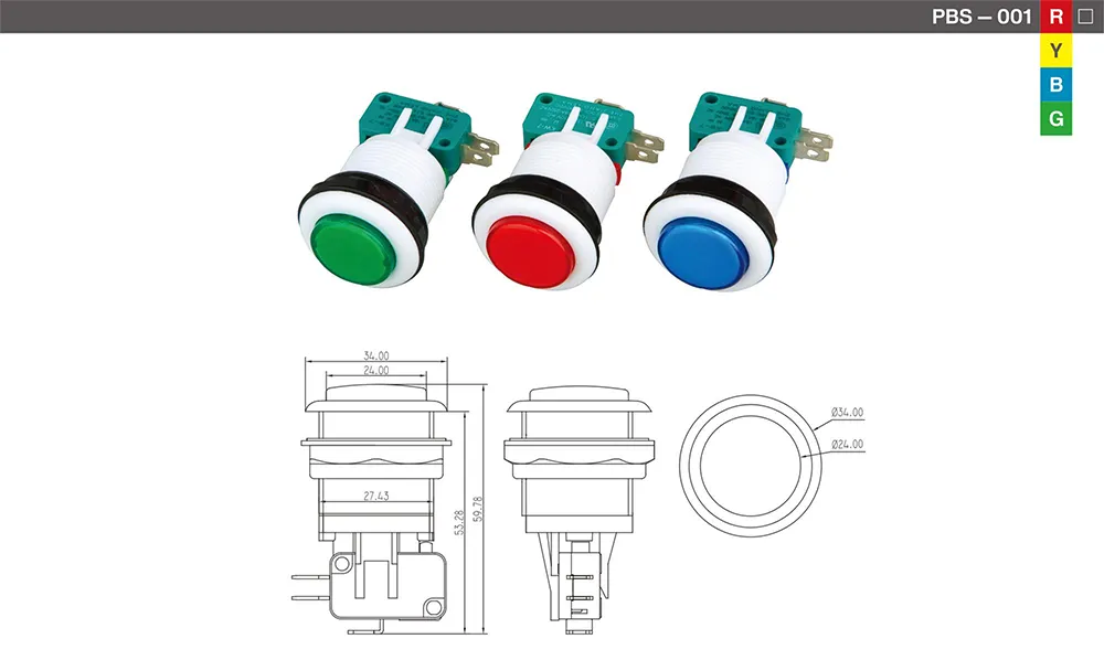
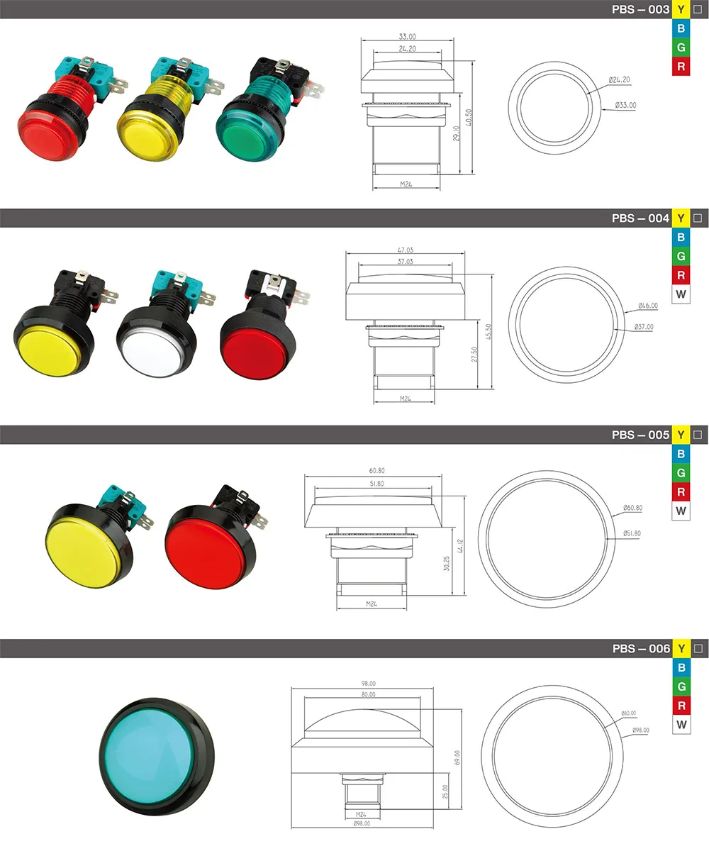
Compare the requirement with the LEMA PBS-series product reference and the broader LEMA push-button range. For simple non-illuminated layouts, the two-pin and four-pin wiring guides explain why pin count alone does not establish function.
FAQ
Are push-button symbols drawn in the pressed position?
Usually they are drawn in the defined normal, unactuated state, but the drawing legend controls. Check the standard and project notes before interpreting the contact.
Does NO mean the machine output is normally off?
No. NO describes the contact path at the device’s normal state. Controller logic, relays and other contacts determine the final machine output.
Is the lamp symbol part of the switch contact?
Not necessarily. In an illuminated button, the lamp or LED normally has its own terminals and rating. Treat it as a separate circuit unless the exact drawing shows an internal connection.
Can a symbol tell me which physical terminal is COM?
Only when terminal references are included and matched to the product drawing. Do not infer the terminal location from a generic symbol or photograph.
Video: NO and NC push-button symbols
This educational video gives a visual introduction to NO and NC contacts, symbols and basic wiring. Use it for concept review; the approved drawing and exact product documentation control the installation.