
A pneumatic foot switch and an electrical foot switch can look similar at the pedal, but they send different kinds of signals. A pneumatic pedal routes compressed air through tubing or operates an air valve; an electrical pedal changes an electrical contact state. The right choice depends on what the machine must control, what utilities are available, and how the pedal will be installed and maintained.
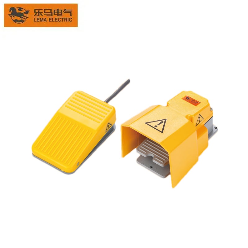
This guide compares the signal path and selection checks rather than treating one type as universally safer or better. LEMA’s LF product family is an electrical foot-switch product; it is included as an example of the electrical option, not as a pneumatic product. Confirm the exact model drawing, contact arrangement, cable, enclosure and ratings before ordering or integrating any foot switch.
Start with the signal the pedal must send
The word “switch” can describe either a device that changes electrical contacts or a valve that changes airflow. Before comparing housing size or price, trace the command from the operator’s foot to the machine:
- Electrical foot switch: pressing the pedal changes one or more electrical contacts. The contact may switch a control input, relay coil or load, subject to the exact switch and circuit ratings.
- Pneumatic foot switch: pressing the pedal changes an air path or sends a pressure signal through a tube. The downstream device may be a pneumatic valve, cylinder or air-operated switch.
- Electro-pneumatic foot switch: air pressure from a pedal actuates a remote electrical switch, combining a pneumatic link at the operator with an electrical output elsewhere.
These are different architectures, not interchangeable wiring versions. AutomationDirect describes electric and pneumatic foot switches as controlling electrical or pneumatic circuits respectively, while Herga describes an air-operated pedal sending a pressure change through tubing to an air switch. Linemaster also distinguishes pneumatic, electro-pneumatic and electrical signal paths in its learning guide.
How the two main types work
In an electrical foot switch, the pedal moves an internal actuator that changes the state of contacts. A momentary model returns when the operator releases the pedal; a maintained model stays in its alternate state until it is actuated again. The contact can be wired into a control input or, if the specifications permit, the switched circuit itself. Do not assume that a pedal intended for a low-current control input can directly switch a motor, solenoid or other inductive load.
In a pneumatic design, the pedal commonly operates a small valve or compresses a bellows. A valve may route supply air to an outlet, vent the outlet, or change a multi-port circuit. A bellows-based design may send a pressure pulse through tubing to a separate air switch. The exact function depends on the port count, valve construction and momentary or maintained action of the selected model. Check a pneumatic diagram rather than inferring the port logic from the pedal shape.
A hybrid electro-pneumatic design uses the air signal to actuate an electrical contact away from the pedal. It can be useful when the pedal area should not contain the electrical switching element, but it adds tubing, an air-operated switch and additional integration points. It should be evaluated as its own architecture rather than treated as a pneumatic valve or a standard wired pedal.
Electrical vs pneumatic foot switch at a glance
| Selection point | Electrical pedal | Pneumatic pedal |
|---|---|---|
| Output from the pedal | Electrical contact state or circuit signal | Airflow, pressure or pneumatic valve state |
| Utilities at the machine | Electrical supply or control wiring | Compressed-air supply and compatible tubing |
| Downstream interface | Controller input, relay, contactor or rated load | Pneumatic valve, actuator or air-operated switch |
| Typical integration work | Wire routing, terminal identification, protection and electrical ratings | Port mapping, pressure range, exhaust, tube routing and leakage checks |
| Primary verification | Contact diagram, voltage/current/load duty and enclosure rating | Valve symbol, ports, pressure, flow and operating action |
The table is a starting point, not a safety ranking. Some electrical models are designed for demanding environments, and pneumatic circuits also have stored-energy and unexpected-motion hazards. Compare the full system and the exact manufacturer documentation.
When an electrical foot switch is a practical fit
An electrical pedal is often straightforward when the machine already has a compatible control circuit and the signal must connect to a controller or relay. It avoids adding an air supply and pneumatic tubing solely for the foot control. A simple dry-contact input may also make status monitoring and fault diagnosis easier, provided the control design handles open circuits, short circuits and contact behavior appropriately.
For production equipment, decide whether the pedal should be momentary or maintained, guarded or exposed, single or dual, and whether the contact will control a low-energy input or a power circuit. Check the actual model’s terminal map, contact form, rated voltage and current, load type, switching frequency, cable entry, mounting and ingress protection. A product-family name or a photograph is not a substitute for the selected model’s datasheet.
Electrical actuation does not automatically make a pedal unsuitable for moisture or dust. The complete assembly, cable entry, connector and installation must meet the environment’s requirements. Select an appropriate rated enclosure and follow the manufacturer’s mounting and wiring directions; never infer a wet-area rating from a plastic or metal cover alone.
When a pneumatic foot switch is worth evaluating
A pneumatic pedal may be worth evaluating when the machine already uses compressed air, when the pedal needs to command a pneumatic valve directly, or when the design requires a pneumatic signal between the pedal and a remote air-operated device. It can avoid routing electrical conductors to the pedal itself, but the system still needs an appropriate air source, pressure regulation, tubing, ports and a defined exhaust path.
Ask how the pedal behaves after loss of air, whether it is spring-return or maintained, whether an air signal can remain trapped, and how the circuit vents during normal release or maintenance. Consider tube length and routing, leakage, contamination, pressure drop, noise and service access. Where the pedal is used in a humid, washdown or potentially explosive area, do not treat “pneumatic” as proof of suitability: verify the full equipment and installation against the applicable site requirements.
Also distinguish a pneumatic control pedal from a safety-rated enabling or emergency-stop device. A foot-operated command can start or control a process; it does not by itself provide safeguarding, redundancy, fault monitoring or a validated stopping function.
Selection checklist for an OEM design
- Define the output: contact state, low-voltage controller input, switched electrical load, pneumatic flow or remote air signal.
- Document the normal state: momentary or maintained action, normally open or normally closed contact if electrical, and the required port state if pneumatic.
- Check the whole duty: voltage, current, inrush, inductive load and switching frequency for electrical contacts; pressure, flow, port logic and exhaust for a pneumatic valve.
- Review the operator interface: pedal size, mounting, accidental-actuation risk, required guard, number of pedals and available foot movement.
- Review the environment: dust, water, cleaning chemicals, temperature, vibration, cable or tube strain relief, and inspection access.
- Plan failure behavior: what the machine does after a broken wire, stuck contact, air leak, loss of pressure, blocked exhaust or disconnected tube.
- Validate the installed system: test the actual machine through its operating modes and confirm that stopping, restart prevention and safeguards meet the machine’s risk assessment.
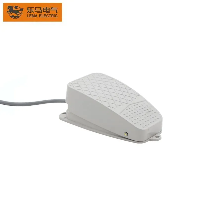
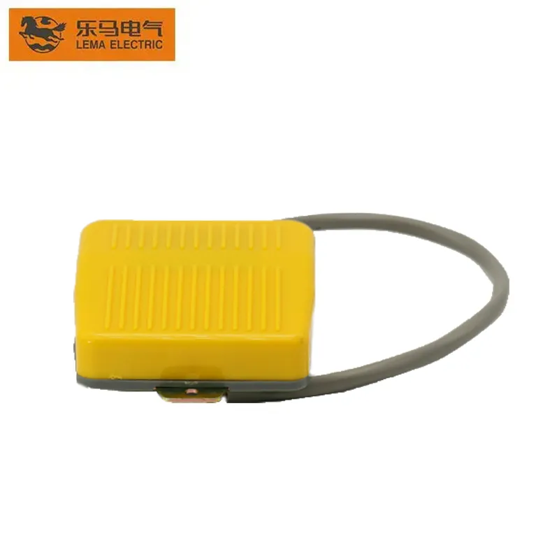
LEMA’s LF-series foot switch product page is a product reference for the electrical-pedal side of this comparison. For related design decisions, see the guides to single- vs dual-pedal foot switches, foot-switch guards and foot-switch IP ratings. The foot switch category links to the product range.
Common questions
Is a pneumatic foot switch the same as an air pedal valve?
Not always. Some pedals contain a valve that directly routes air; others use a bellows to send a pressure signal to a separate air switch. Check the product diagram, port count and downstream interface.
Can an electrical foot switch control a pneumatic cylinder?
It can command an electrical solenoid valve in a properly designed control circuit, but that is an electrical-to-pneumatic system. Verify the control voltage, valve coil, contact or output rating, suppression and machine safety design.
Is a pneumatic foot switch always safer in a wet area?
No. It removes electrical switching conductors from the pedal in some designs, but tubing, the downstream valve, cleaning method, pressure and mechanical hazards still need review. Verify suitability of every component and the complete installation.
Which type should an OEM choose?
Choose by the signal the machine needs, available utilities, environment, failure behavior, service plan and verified model ratings. Prototype and validate the complete machine rather than selecting by pedal appearance or a generic product label.
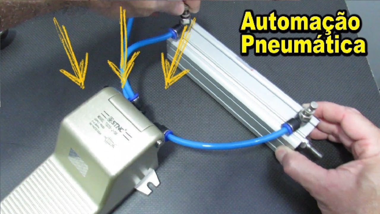
Video: pneumatic pedal-valve operation
This general training demonstration illustrates a pneumatic pedal valve. It is not a LEMA product specification; use the selected model’s drawing and documentation for a real design.
External references: AutomationDirect foot-switch overview; Herga pneumatic footswitches; Linemaster guide to pneumatic, electro-pneumatic and electrical foot switches.