A mushroom push button switch uses a wide, prominent actuator that is easy to locate and press, but head shape alone does not make it an emergency-stop device. Select it by intended command, maintained or momentary action, contact arrangement, color, legend, panel fit, electrical duty and required safety function. A general machine-control button and a compliant emergency-stop operator may look similar while having different latching, reset, contact and certification requirements.
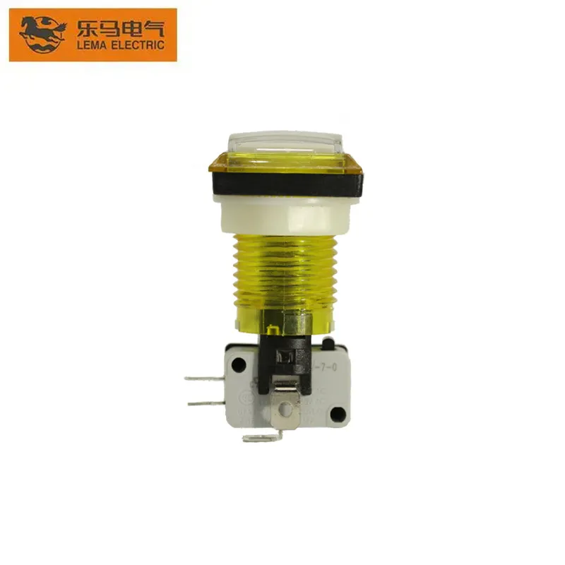
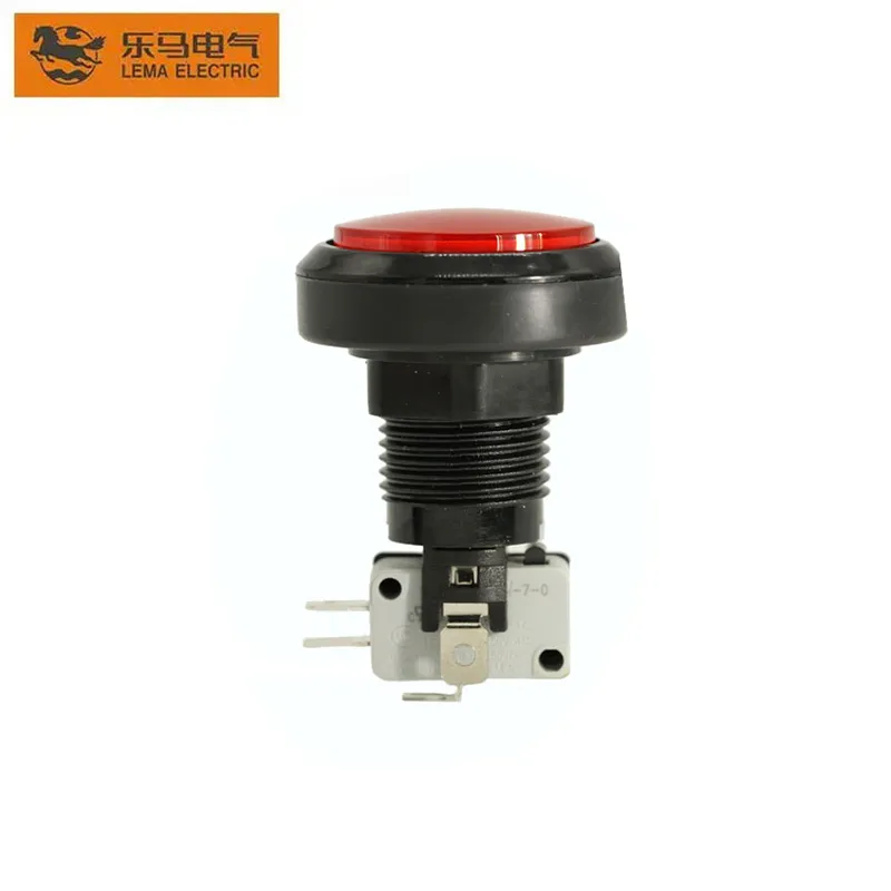
This guide separates those uses and provides an OEM selection process. LEMA PBS-series photos are real product references for a domed push-button form; confirm the exact model drawing and approvals before specifying any safety-related function.
Selection table
| Decision | General mushroom button | Emergency-stop application | Evidence required |
|---|---|---|---|
| Purpose | Large manual command | Stop hazardous motion in defined conditions | Machine risk assessment and control narrative |
| Action | Momentary or maintained | Typically latching with deliberate reset | Exact mechanical action and reset method |
| Contacts | NO, NC or changeover as required | Safety architecture may require specific NC/direct-opening contacts | Contact diagram and compliance documentation |
| Color/marking | Chosen for machine convention | Governed by applicable standards and project rules | Panel design and standard review |
| Validation | Functional and endurance checks | Complete safety-function validation | Test plan and recorded results |
Why the large head is useful
A broad actuator is easier to find with a hand, glove or palm than a small flush button. It can suit start, stop, acknowledge, cycle request or other commands where visibility and a generous target area are valuable. The shape can also reduce the precision needed for actuation.
That advantage creates a trade-off: a projecting head may be struck accidentally. Consider guards, shrouds, spacing and panel location according to the command. A guard must not make an intended urgent action difficult. Test the layout with representative operators, gloves, lighting and viewing angles.
Momentary, maintained and latching action
A momentary button returns when pressure is removed. A maintained button changes state and stays there until another operation. A latching emergency-stop operator usually remains actuated and requires a defined reset action such as twist or pull. These terms are not interchangeable.
Write what the machine must do on press, hold, release, reset and power restoration. Resetting a physical button should not automatically restart hazardous motion. The control system must enforce the machine’s required restart behavior independently of the operator’s appearance.
NO and NC contacts
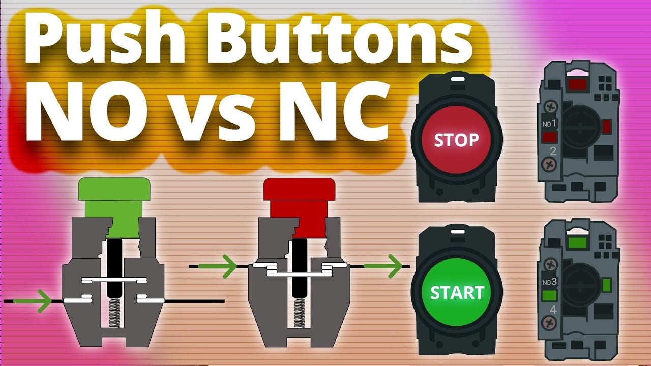
Normally open contacts close when actuated; normally closed contacts open. A command can use one or both, and illuminated assemblies may add lamp terminals. Use the exact contact diagram because pin count and physical location do not prove function. The push-button symbol guide explains NO, NC and lamp representations.
With power isolated, verify continuity in rest and actuated states. For safety functions, ordinary continuity is not enough: contact mechanism, direct-opening behavior, redundancy, diagnostics and the whole circuit must meet the applicable design and validation requirements.
Emergency stop is a system function
The ISO 13850 standard page identifies the machinery emergency-stop design principles standard. The OSHA machine-guarding eTool provides broader guarding context. Determine the applicable requirements for the machine, market and jurisdiction.
A red mushroom head does not prove compliance. The stop category, contacts, control architecture, reset, placement, identification, fault response and validation all matter. Do not advertise a general PBS button as an emergency-stop device without the exact product evidence.
Color, marking and operator meaning
Use colors consistently across the equipment. Do not rely on color alone; add a clear legend, symbol or text where required. Consider color-vision differences, grime, low light and multilingual operation. The command should remain understandable when the lamp is off.
Place related buttons in a logical group while keeping critical stop controls clearly distinguishable. Avoid identical mushroom heads for contradictory functions on the same panel unless the panel standard and labeling remove ambiguity.
Panel cutout and mechanical fit
Confirm mounting-hole diameter, maximum panel thickness, anti-rotation feature, bezel clearance, nut arrangement and space behind the panel. The actuator must move freely after tightening. A thin flexible panel can distort or vibrate; reinforce it when required.
Leave room for contact blocks, wiring, lamp modules and service tools. The 2-pin push-button wiring guide helps separate basic contact wiring from panel mechanics, but the controlled drawing for the exact model remains authoritative.
Electrical load and interface design
Match voltage, AC/DC duty, current, load type and operating rate. A button suitable for a PLC input may not be suitable for a contactor coil, lamp inrush or motor. Use a relay, controller input or other interface when the documented button rating does not directly cover the load.
Inductive loads can create opening transients, so suppression may be needed at the coil or interface. Keep control and power circuits appropriately separated, protect terminals from accidental contact and use conductor sizes and terminations approved for the assembly.
Illumination and feedback
An illuminated mushroom button can show availability, command acceptance or machine state, but the meaning must be defined. Do not wire the lamp merely in parallel with the command and assume it proves the output acted. When confirmation matters, drive indication from monitored machine state.
Specify lamp voltage, polarity for LEDs, color, brightness, expected ambient light and replaceability. Review the 4-pin push-button wiring guide for separating switch and lamp circuits. Always verify the exact pinout.
Ingress and environmental conditions
Panel-front sealing does not automatically cover rear terminals or the whole enclosure. Define dust, water, oil, temperature, vibration, UV and cleaning chemicals. Confirm the rating after installation with the specified seal, panel surface and tightening method.
If the button will be struck, leaned on or cleaned frequently, include mechanical abuse and cleaning in the prototype test. Replace cracked, sticky or faded operators rather than relying on uncertain field repairs.
Commissioning checklist
- Confirm part number, action, color, legend and contact arrangement.
- Verify cutout, panel thickness, anti-rotation and tightening method.
- Test every contact with power isolated.
- Confirm lamp circuit voltage and polarity where fitted.
- Check accidental-operation risk and accessibility with gloves.
- Test press, release, latch, reset and power-restoration behavior.
- Validate any safety function as a complete system.
- Record final wiring, model and inspection criteria.
Usability and maintenance checks
Run a short usability trial with the real panel height, operator position and protective gloves. Observe whether users can identify the correct button without hesitation, whether nearby controls are struck at the same time, and whether the head can be reached from expected work positions. Correct label placement or spacing before production tooling is frozen.
During maintenance, inspect the actuator for sticking, cracks, looseness, faded marking and contamination around the bezel. Confirm contact state and mechanical return after cleaning. Do not lubricate or modify the mechanism unless the manufacturer specifies the method. Replace a damaged operator or contact block with the controlled part number, then repeat the functional test.
Common specification mistakes
Avoid requests such as “red mushroom, 22 mm, emergency type” without contact, action or compliance details. The same visual description can cover a momentary command button, a maintained selector-like operator or a safety-oriented latching device. Another mistake is choosing lamp voltage from the control supply while overlooking polarity, resistor configuration or separate lamp terminals.
Finally, do not use the button’s current rating as permission to switch any load of the same amperage. Inrush, inductance and DC interruption can dominate contact stress. Define the actual load and interface, then obtain the matching rating evidence.
OEM RFQ checklist
State the command purpose, mushroom diameter, color, marking, momentary or maintained action, latch/reset method, NO/NC contacts, direct-opening or safety evidence if required, illumination, voltage and load, panel cutout, thickness, terminal type, environmental rating, expected cycles and required approvals. Compare with the LEMA PBS product reference and broader push-button range.
FAQ
Is every red mushroom button an emergency stop?
No. Appearance and color do not prove the required latching, contact, standard or safety-system performance.
Should a mushroom button be momentary or maintained?
Choose from the command. General controls may use either; an emergency-stop function normally requires defined latching and reset behavior under applicable standards.
Can a mushroom button switch a motor directly?
Only if the exact product has a suitable motor rating. Usually the button commands a controller, relay or contactor.
Does resetting the button restart the machine?
It should not automatically restart hazardous motion. Restart behavior must be defined and validated in the control system.
Video: push-button contact operation
This educational video explains NO and NC push-button behavior. It does not certify a product for emergency-stop use.