
A push button contact block is the part of an operator assembly that changes one or more electrical contact states when the button moves. Before choosing or replacing one, identify whether the product is genuinely modular or has an integral switching mechanism, then match the contact function, operator family, mounting method, terminal layout and electrical duty. Button color alone does not tell you whether a circuit is normally open or normally closed, and a block that looks similar is not necessarily mechanically or electrically compatible.
What a contact block does
In a modular industrial control station, the front operator is pressed or turned while one or more contact blocks mounted behind it open or close electrical paths. The blocks may provide normally open (NO), normally closed (NC), changeover or multiple independent contacts, depending on the exact design. A stack can combine several contacts for a control circuit, indicator, interlock input or other documented purpose.
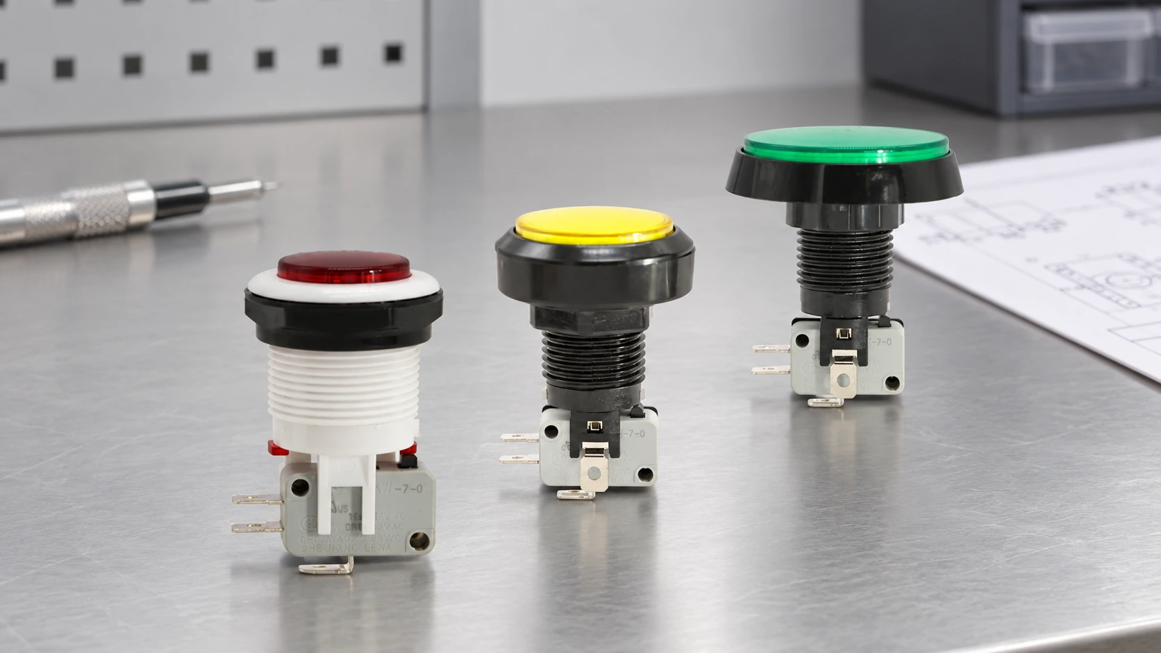
Not every push button uses a separate removable contact block. Some products contain a built-in microswitch or an integrated switching assembly. The physical location of terminals at the rear does not establish that the module can be detached, replaced or combined with another operator. First identify the product architecture from a parts drawing or instruction sheet. This distinction matters especially when maintenance staff use “contact block” as a generic name for any rear contact mechanism.
Read NO and NC from the unactuated state
NO and NC describe the contact condition when the operator is in its specified normal, unactuated state. A normally open contact is open at rest and changes state when the operator is pressed; a normally closed contact is closed at rest and opens on actuation. Always use the device manufacturer’s definition and circuit drawing when the mechanism has latching, selector, pull-to-release or other special behavior. “Normal” is not the same as “machine off,” “safe,” or “operator has stopped.”
A button’s cap color is a separate interface choice. Color can help communicate an intended function under the applicable machine and workplace conventions, but it does not reveal the contact arrangement or prove a safety function. Verify the contact code and the circuit behavior in the drawing. For example, a green start command often uses a momentary NO contact and a stop command often uses a momentary NC contact in a control circuit, but the correct design depends on the machine’s complete control architecture and applicable requirements.
Separate contact function from contact rating
NO or NC answers which way the contact changes state; it does not say what voltage, current or load the contact may switch. Rating, utilization category, minimum load, electrical life and terminal requirements are separate checks. A contact intended for a low-energy logic input may have different constraints from a control contact that switches a relay coil. Never infer a rating from the color of a plastic carrier, terminal size or the rating of a different manufacturer’s block.
Independent references can help with terminology, but none replaces the selected product’s drawing. The open BCcampus Basic Motor Control chapter explains momentary pushbuttons and NO/NC contacts in a control circuit. Electrical Academia’s contact-block overview illustrates modular contact arrangements and replacement in some designs. For color-coded machine signals, consult the applicable requirements; the official IEC 61310-1 scope addresses visual, acoustic and tactile safety information, not the electrical contact arrangement of a particular button. These general sources do not establish compatibility with a LEMA product.
Use a compatibility checklist before replacement
| Compatibility area | What to compare on the exact documentation | Why it matters |
|---|---|---|
| Operator family | Manufacturer, series, operator model and approved contact-block family | Similar-looking parts may use different latches, keys, holders or movement. |
| Contact arrangement | Number of NO, NC or changeover contacts and their normal/operated states | The replacement must preserve the intended control logic. |
| Mechanical interface | Mounting position, stack direction, holder, keying and operating travel | A block may not latch or actuate correctly on another operator. |
| Electrical duty | Voltage, current, load type, control category and minimum-load limits | Matching contact labels does not guarantee the required switching capacity. |
| Connections | Screw, spring, push-in, solder or plug-in terminals; wire range and orientation | Terminal fit and conductor preparation affect installation and inspection. |
| Environment and approvals | Temperature, contamination, enclosure needs and required product approvals | The block is part of an assembly exposed to its actual installation conditions. |
| Safety function | Required fault behavior, direct-opening claims and system-level validation | A general contact block is not automatically a safety-rated control. |
This table is a verification checklist, not a universal interchangeability rule. Do not treat “22 mm,” a shared color, or the same NO/NC marking as enough evidence. Ask for the manufacturer’s compatibility statement or an exact cross-reference tied to both operator and block part numbers. If the supplier cannot confirm a replacement, identify the complete operator assembly rather than fitting a visually similar spare.
For a starter or contactor control station, the push button normally sends a command through the control circuit; it is not automatically the device that switches motor power. The BCcampus three-wire control lesson presents a general start/stop arrangement with separate push-button contacts and a motor starter. Treat it as educational context, not a wiring instruction for a different machine. The machine schematic and applicable electrical rules govern the real installation.
What LEMA’s PBS images do—and do not—confirm
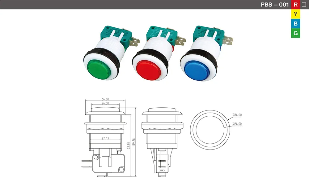
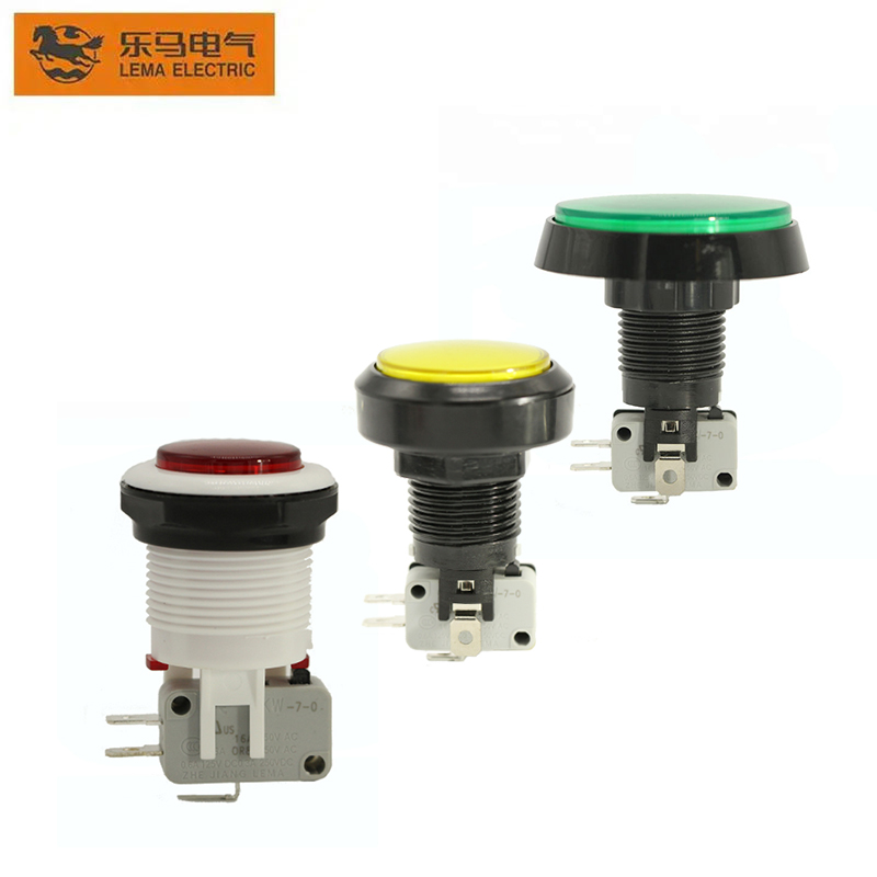
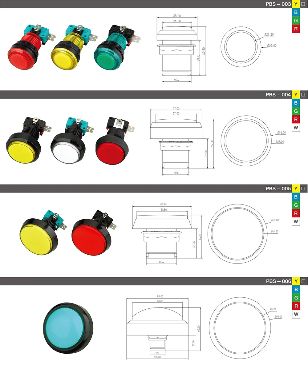
The LEMA PBS Series product page and its product-library images show complete push-button examples, including rear switching mechanisms. They are useful for confirming the product category and visible assembly style. The images alone do not document a universal detachable contact block, an interchangeable third-party base, a particular NO/NC arrangement for every model, or a replacement part number. Do not market or order a standalone block for this series until LEMA confirms the exact model architecture and spare-part compatibility in writing.
Inspect and replace a block safely
Before inspection or replacement in installed equipment, isolate the relevant energy sources, follow the machine’s lockout procedure and verify the circuit is de-energized using the site’s approved method. Electrical work should be performed by qualified personnel. Mark conductors before removal, compare the old and new part numbers, and photograph the original terminal arrangement. A color or terminal position should never be used as the only wiring record.
For a non-energized contact check, follow the manufacturer’s instructions and use a continuity meter to verify the rest and operated states. Check each pole independently and confirm the actuator fully returns or latches as specified. This simple check can detect an incorrect NO/NC block or a mechanical mismatch, but it does not prove insulation performance, electrical rating, endurance, safety compliance or suitability for a live load. Recommission the finished circuit using the machine builder’s validation procedure.
Contact failure may come from wear, contamination, a poor terminal connection, an overloaded contact, an incorrect suppression method or a fault elsewhere in the control. Replacing only the visible block without diagnosing the circuit can reproduce the failure. Record the reason for replacement, the model and the observed contact state so the maintenance history informs the next investigation.
Questions to include in a purchasing request
- What is the complete operator part number and product family?
- Is the switching mechanism modular and separately replaceable, or integral to the assembly?
- What contact arrangement is supplied, and what is the NO/NC state at rest?
- What mounting holder, block position and actuator travel are required?
- What voltage, current, load type and minimum-load condition apply?
- Which terminal style and conductor range are needed?
- Does the assembly have a required enclosure, environmental rating or approval?
- Can the supplier provide a current drawing, instructions and written replacement cross-reference?
For related selection context, see LEMA’s industrial push-button selection guide, the NO-versus-NC push-button explanation and the push-button symbol guide. These topics explain operator choice and schematic notation; none replaces the exact part’s contact-block documentation.
How a contact block moves
The short video below shows a generic industrial switch contact-block assembly and a mechanical actuation-force demonstration. It is useful for visualizing how a contact stack can move with an operator, but it is not a LEMA compatibility guide or a test of LEMA product ratings. Use the exact model drawing and specifications when selecting or replacing parts.
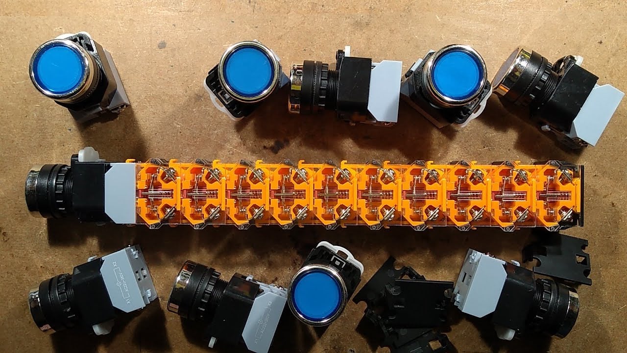
Watch the contact-block demonstration on YouTube.
Frequently asked questions
Does the button’s color identify whether its contact is NO or NC?
No. Color is a visual interface choice. Read the contact code and drawing for the exact model to determine the normal and operated states.
Can contact blocks from different brands be interchanged?
Not without an exact compatibility statement. Mounting keys, travel, terminal position, ratings and operator family can differ even when the blocks look alike.
Can every push button have its contact block replaced separately?
No. Some products use a modular block while others have an integral switching mechanism. Confirm the product architecture and approved spare parts for the exact model.
Does an NC contact automatically make a stop circuit safe?
No. NC describes a contact’s state under specified conditions; machine safety depends on the complete control system, risk assessment, required components and validation.