LEMA NEWS CENTER

News & Blog

News Center

IEC Power Inlet Creepage and Clearance: Assembly Review
Blog LEMA Electric

IEC Power Inlet Creepage and Clearance: Assembly Review

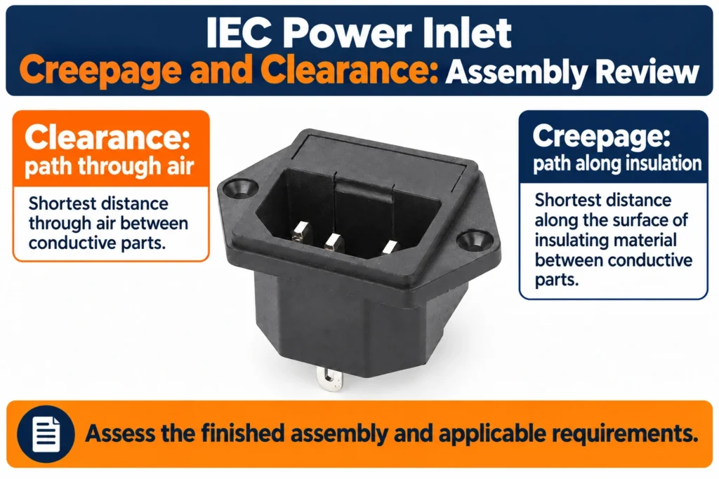
IEC power inlet creepage and clearance must be assessed in the finished assembly as well as within the component. Clearance is the shortest relevant path through air; creepage follows the relevant insulating surface. Panel screws, wire routing and nearby conductive parts can change the assembly paths. There is no universal spacing that can be selected from mains voltage alone.The IPZ Series AC Power Socket is the LEMA product reference illustrated here. Its photograph identifies the external product, not an unlisted rating, accessory compatibility or test result. Obtain the current specification for the full order code before approving an assembly. Begin with the electrical design of the completed equipment. Identify the conductive parts at each side of the relevant boundary and the function that the insulation provides. The inlet terminals, enclosure, mounting hardware, adjacent components and connected wiring may all be relevant. Measuring the most visible gap without defining the boundary can produce a precise number for the wrong question. Keep the component boundary distinct from the equipment boundary. An inlet can have documented construction and approval conditions while the finished installation still introduces another path through a nearby screw, bracket or wire. Obtain the current inlet drawing and the conditions applicable to the exact variant, then review how it is installed in the actual enclosure. Distinguish a path through air from one along a surface Clearance concerns the relevant shortest path through air between conductive parts. Creepage concerns the relevant shortest path along an insulating surface. These measurements can follow different routes around the same pair of parts. A large visible space in front of a component does not establish the shortest path behind it or along its supporting material.Show...

Read More
Switch Incoming Inspection: Lot Sampling and Acceptance
Blog LEMA Electric

Switch Incoming Inspection: Lot Sampling and Acceptance

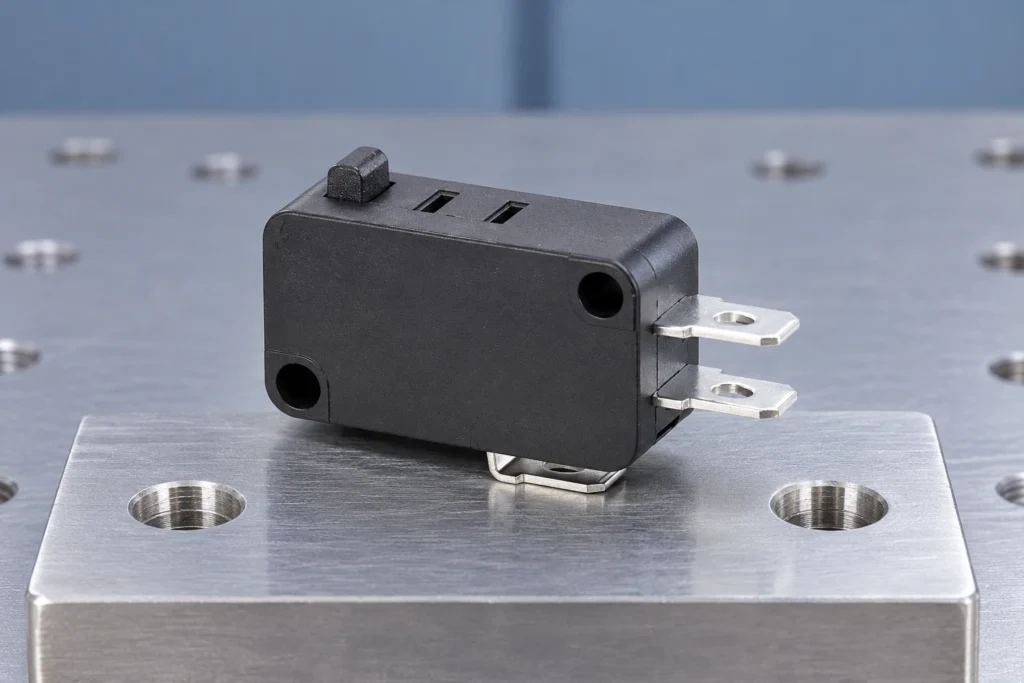
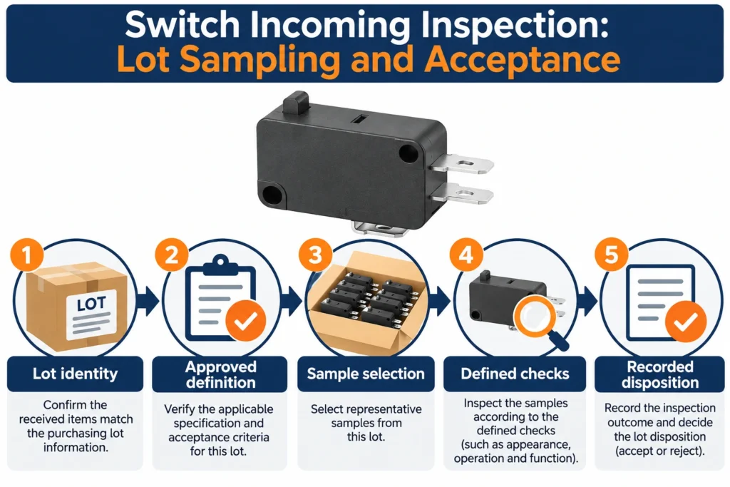
Electromechanical switch incoming inspection should connect each received lot to the approved part definition and a written acceptance procedure. Define the lot, select samples by the agreed plan, check identity and relevant performance, and record the disposition. A supplier certificate alone is not an executed inspection, while an accepted sample does not prove every unit is defect-free.The KW7 Series Micro Switch is the LEMA product reference illustrated here. Its photograph identifies the external product, not an unlisted rating, accessory compatibility or test result. Obtain the current specification for the full order code before approving an assembly. A lot needs a traceable boundary. Record the complete part code, supplier, purchase order, received quantity and available manufacturing or packaging identifiers. Do not combine different contact variants, terminal options or date-code groups merely because the cartons share a family name. If a shipment contains several identified lots, the receiving procedure should explain how each is represented in the inspection decision. Keep the relationship between the physical material and the receiving record intact when cartons are opened. Repacking, kitting and production returns can remove that relationship unless the process preserves it. A receiving label should identify the material actually covered by the record. It should not imply that an uninspected additional shipment shares the same result. Establish the approved part definition Inspect against the agreed specification and drawing revision, rather than a photograph copied from an old quotation. The full code can identify a contact arrangement, terminal style, actuator or operating characteristic that is not obvious from the exterior. Include approved substitutions and their conditions in the controlled record so the inspector can distinguish a permitted option from an undocumented change. Check the order,...

Read More
Micro Switch Minimum Load: Validate Low-Level Signals
Blog LEMA Electric

Micro Switch Minimum Load: Validate Low-Level Signals

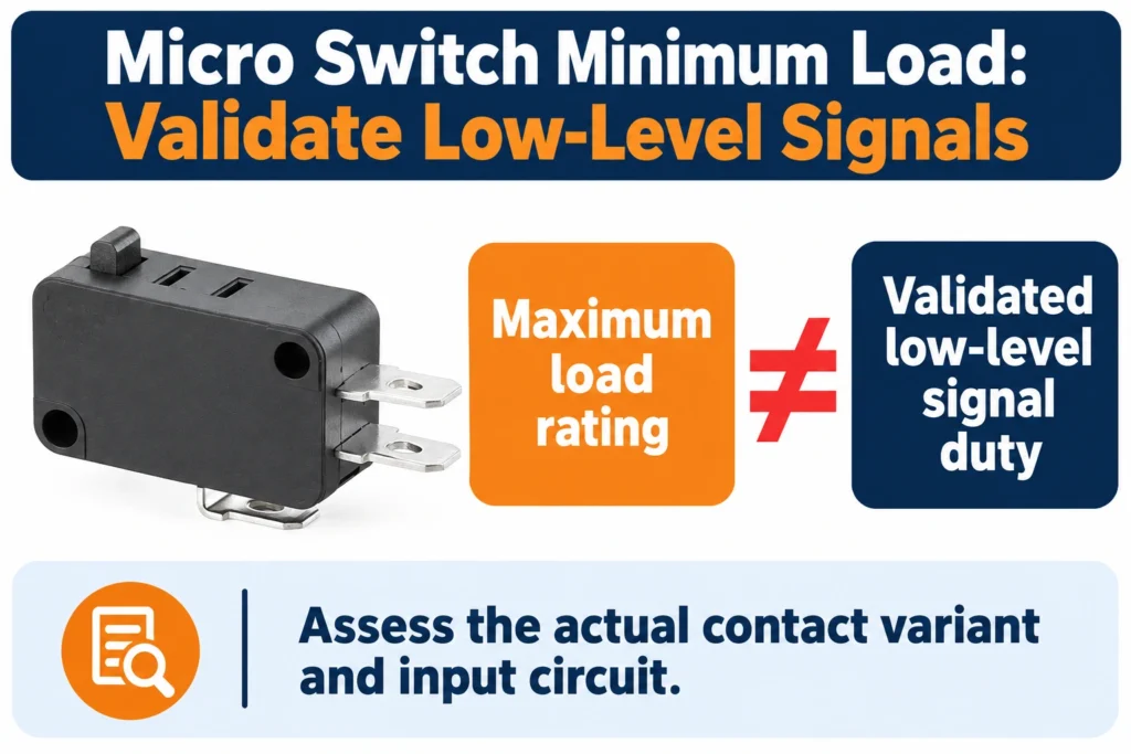
Micro switch minimum load describes the lower switching conditions supported by a particular contact system under stated test conditions. A maximum current rating does not establish reliable operation at a tiny signal level. Validate the actual input circuit, contact variant, environment and required reliability rather than assuming that every power-rated switch is suitable for a dry circuit.The KW7 Series Micro Switch is the LEMA product reference illustrated here. Its photograph identifies the external product, not an unlisted rating, accessory compatibility or test result. Obtain the current specification for the full order code before approving an assembly. Why an Upper Rating Does Not Establish a Minimum Load An upper electrical rating describes an allowable switching duty under stated conditions. It does not automatically identify the lowest voltage or current at which the contact will function reliably. A contact arrangement that performs satisfactorily with an energetic load may depend partly on electrical effects that are absent in an electronic sensing circuit. Reading the upper rating backward creates an unsupported assumption: that anything electrically smaller must be easier. At low signal levels, contact resistance can become unstable because the conducting interface is influenced by films, surface condition, contact force, and microscopic contact spots. The receiving input may interpret that instability as an open circuit, delayed transition, or intermittent state. Meanwhile, the switch may still operate mechanically and sound normal. Mechanical action alone does not demonstrate electrical suitability for the application. When documentation gives a minimum applicable load or a low-level designation, examine its scope. Ask which contact construction, environment, operating history, and acceptance method support the statement. A published designation is useful evidence, but it is not permission to substitute different terminal finishes,...

Read More
Micro Switch Terminal Strength: Mating and Pull-Test Boundaries
Blog LEMA Electric

Micro Switch Terminal Strength: Mating and Pull-Test Boundaries

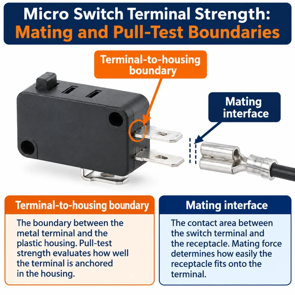
Micro switch terminal mechanical strength is not the same as connector mating force or cable retention. A receptacle can hold a wire securely while its installation bends the switch blade or loads the housing. Define which interface is being assessed, the direction of force and whether the test is destructive before setting an acceptance procedure.The KW7 Series Micro Switch is the LEMA product reference illustrated here. Its photograph identifies the external product, not an unlisted rating, accessory compatibility or test result. Obtain the current specification for the full order code before approving an assembly. Separate Mating Force, Retention, and Terminal-to-Housing Strength Mating force is the force needed to engage a receptacle or connector with the switch terminal. It reflects contact geometry, spring action, alignment, friction, and any locking feature. It matters during assembly because the mating load must pass through the terminal and its supporting structure. A connection that feels secure after assembly may still impose an unsuitable insertion load, especially when the operator pushes at an angle or cannot support the switch body. Retention describes resistance to separation after mating. For a push-on receptacle, this may come from spring contact pressure, a positive latch, or both. Retention must be evaluated using the specified mating component and an appropriate disengagement method. Pulling an unlocked connector, pulling against an engaged latch, and operating a release feature measure different behaviors. None should be substituted for another without an explicit engineering rationale. Terminal-to-housing strength concerns the attachment of the terminal within the switch itself. Loads may be resisted by formed features, molded material, internal supports, or other construction details. This interface can be damaged even when the mating connector remains intact. Terminal movement,...

Read More
Break-Before-Make Toggle Switch: Verify Transfer Timing
Blog LEMA Electric

Break-Before-Make Toggle Switch: Verify Transfer Timing

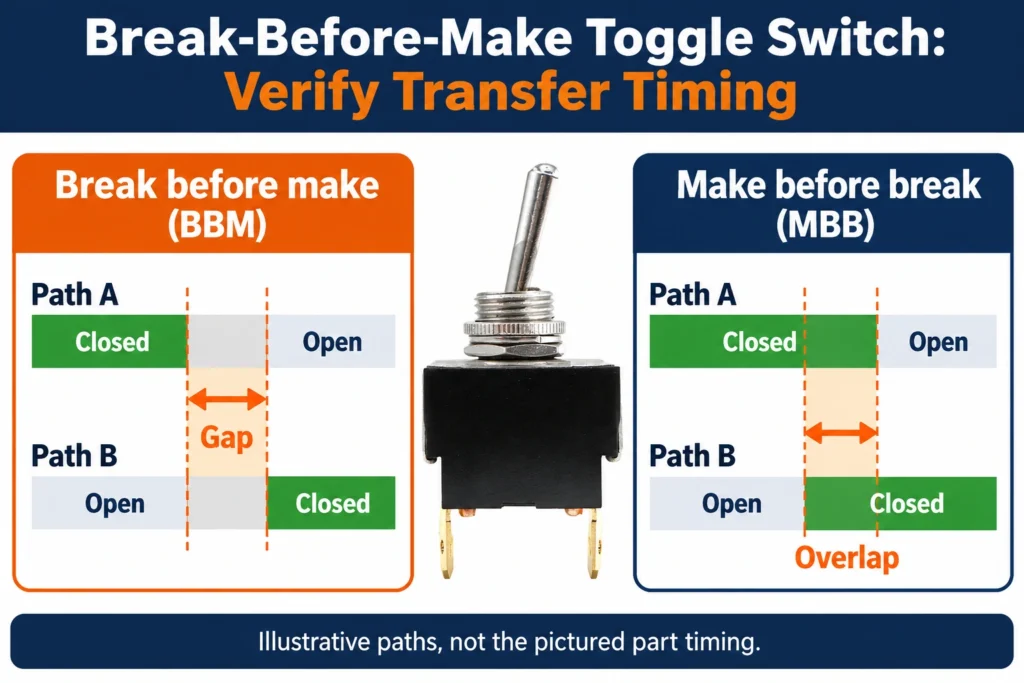
A break-before-make toggle switch disconnects the previous path before connecting the next path during transfer. A make-before-break action allows a period of overlap instead. The stable terminal diagram and the presence of a center-off position do not by themselves define every timing detail. Obtain variant-specific transition information and validate the circuit requirement.The LEMA LT2210C ON-OFF-ON 3 Position DPDT Heavy Duty Toggle Switch is the LEMA product reference illustrated here. Its photograph identifies the external product, not an unlisted rating, accessory compatibility or test result. Obtain the current specification for the full order code before approving an assembly. Stable States Describe Positions, Not the Journey Transition timing must therefore be treated as a separate characteristic. The relevant questions include whether the departing contact opens before the arriving contact closes, whether either contact rebounds, and whether an apparently open path remains electrically significant to the application. Position labels cannot answer these questions. Neither can a static continuity check performed only after the actuator has settled. The OEM should distinguish the switch’s contact truth table from its dynamic contact behavior throughout the qualification record.Explain why stable contact states do not specify transfer order. Product-reference teaching illustration; no measured result or approved installation is depicted. BBM and MBB Describe Different Event Orders Break-before-make, often abbreviated BBM, requires an open interval between the relevant departing and arriving conductive states. Make-before-break, or MBB, deliberately establishes the arriving path before releasing the departing path. The resulting overlap may be useful where continuity must be maintained, but it can be unacceptable where alternate sources, signals, or operating modes must remain separated. Neither sequence is universally better; suitability depends on what the circuit permits during transfer. The phrase “non-shorting”...

Read More
Electromechanical Switch Storage: Shelf Life and Lot Release
Blog LEMA Electric

Electromechanical Switch Storage: Shelf Life and Lot Release

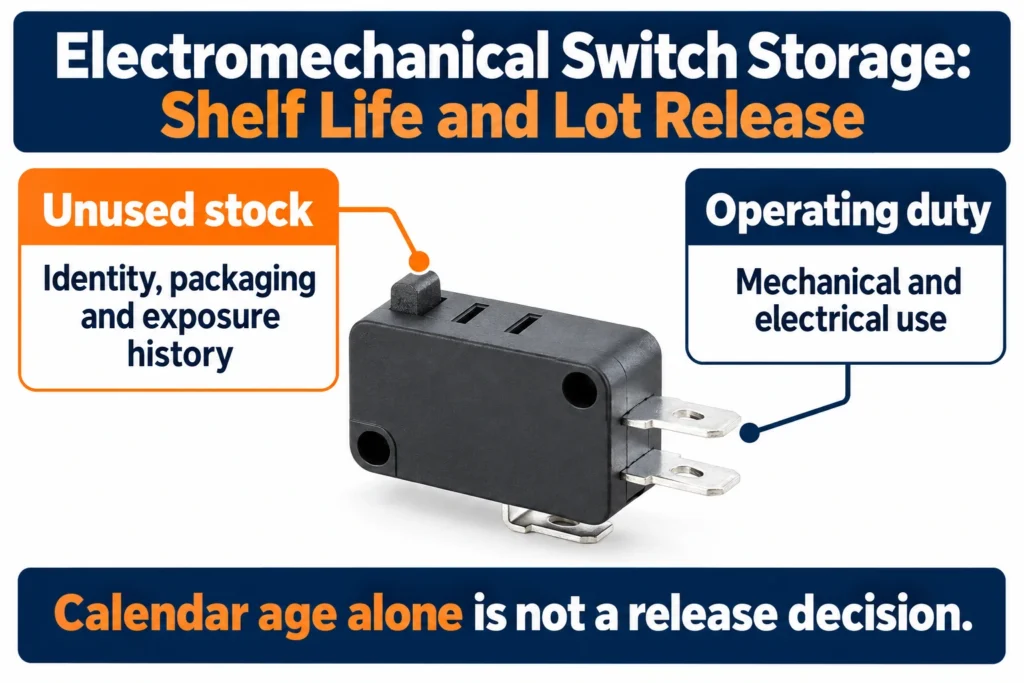
Electromechanical switch storage shelf life cannot be inferred from mechanical life, the shipping date alone or a universal expiry rule. Follow the exact supplier storage instructions and assess package condition, exposure history and the intended assembly process. Older unused stock may need a documented review, but elapsed time by itself neither approves nor rejects a lot.The KW7 Series Micro Switch is the LEMA product reference illustrated here. Its photograph identifies the external product, not an unlisted rating, accessory compatibility or test result. Obtain the current specification for the full order code before approving an assembly. Storage Shelf Life Is Different From Operating Life Operating life concerns performance during use. It may involve mechanical cycling, contact wear, electrical loading, arcing, actuator fatigue, or changes in switching characteristics. Storage shelf life concerns whether an unused component remains suitable after time in inventory. These are related reliability considerations, but they are not interchangeable specifications. An unused switch has not consumed its rated operating endurance simply by sitting in a warehouse. Nevertheless, storage can affect terminal surfaces, exposed contacts, seals, lubricants, plastics, and packaging. A satisfactory cycling result does not automatically establish solderability, and acceptable solderability does not establish endurance under the intended electrical load. Keep these distinctions explicit in purchasing requirements and inspection plans. Avoid converting an operating-life statement into a storage approval or assuming that a switch with no visible wear must be ready for production. Acceptance should address the mechanisms relevant to storage and the demands of the manufacturing process. Read Lot Age Alongside Condition and History A date code can help identify manufacturing history, but its meaning depends on the supplier’s coding system. It may not identify packaging, shipment, receipt,...

Read More
Micro Switch Humidity and Condensation: Validate the Environment
Blog LEMA Electric

Micro Switch Humidity and Condensation: Validate the Environment

Micro switch humidity and condensation are different exposure questions. Relative humidity describes the air at a particular temperature; condensation depends on whether a surface reaches conditions where water can form. An ingress rating alone does not establish that an installed mechanism will remain free of internal or external condensation. Review temperature transitions and the complete installation.The KW7 Series Micro Switch is the LEMA product reference illustrated here. Its photograph identifies the external product, not an unlisted rating, accessory compatibility or test result. Obtain the current specification for the full order code before approving an assembly.KW7 closed housing and terminals on a dry inspection mat. Product-reference illustration, not a test result or installation drawing. Relative Humidity Versus Dew Point Relative humidity describes how close air is to saturation at its current temperature. It changes when air warms or cools, even if the amount of water vapor remains unchanged. This makes a humidity reading useful but incomplete. Air sampled near a warm controller may appear relatively dry while a nearby metal bracket, door panel, or switch terminal is cold enough to collect moisture. Dew point is the temperature at which the sampled air becomes saturated. Condensation becomes possible when a surface reaches or falls below the dew point of the air contacting it. The important comparison is therefore between local dew point and local surface temperature, not simply between a cabinet humidity reading and a general environmental specification. Temperature differences inside an assembly can matter more than the average cabinet condition. For troubleshooting, record air temperature and humidity near the switch while also observing the temperature of representative surfaces. Pay particular attention to parts connected thermally to the outside environment. A mounting...

Read More
Limit Switch Cable Gland Selection: Entry and Cable Fit
Blog LEMA Electric

Limit Switch Cable Gland Selection: Entry and Cable Fit

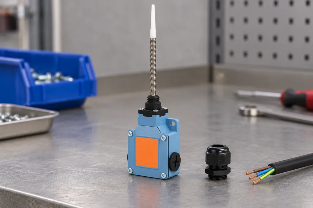
Limit switch cable gland selection requires matching the actual enclosure entry, cable jacket and assembly requirements. The entry thread and the cable sealing range are separate checks. A gland that screws into the housing can still fail to grip or seal the cable correctly. Confirm the controlled drawings and installation instructions before choosing an accessory.The LZ1 Series Limit Switch Durable Aluminum Alloy Body IP66 Rated is the LEMA product reference illustrated here. Its photograph identifies the external product, not an unlisted rating, accessory compatibility or test result. Obtain the current specification for the full order code before approving an assembly.LZ1 closed side-entry plug and cover on an inspection bench. Product-reference illustration, not a test result or installation drawing. Identify the Enclosure Entry Before Selecting Hardware Begin with the switch enclosure drawing and the supplier’s entry instructions. Establish whether the opening is threaded or intended for a through-mounted gland with a locknut. For a threaded opening, identify the thread form, pitch, engagement requirements, and the sealing arrangement specified for that interface. Similar-looking threads can start together yet fail to engage correctly or leave an unsuitable sealing condition. Do not use assembly torque to compensate for a mismatched thread. Resistance during installation may indicate cross-threading, damaged coatings, debris, or incompatible geometry rather than a properly seated connection. Obtain an authoritative entry specification when the drawing is incomplete. Checking a loose sample alone can be misleading if production enclosures come from different tooling or finishing processes. Examine the exterior and interior seating surfaces. A sealing washer needs a suitable contact face, while a locknut needs room to seat without colliding with internal parts. Thin walls, curved surfaces, recessed entries, casting texture, and nearby...

Read More
Micro Switch Mounting Screw Torque: Prevent Housing Distortion
Blog LEMA Electric

Micro Switch Mounting Screw Torque: Prevent Housing Distortion

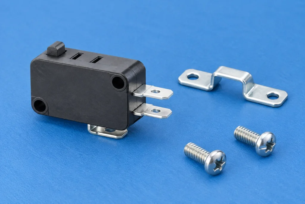
Micro switch mounting screw torque must be set for the exact switch, supporting surface and fastener stack. Screw diameter alone cannot establish a safe setting. A housing can be secure yet distorted enough to change actuator behavior. Review the intended mounting features, load path and installed function before approving the assembly.The KW7 Series Micro Switch is the LEMA product reference illustrated here. Its photograph identifies the external product, not an unlisted rating, accessory compatibility or test result. Obtain the current specification for the full order code before approving an assembly.Closed KW7 housing and mounting holes beside a detached caliper. Product-reference illustration, not a test result or installation drawing. Why There Is No Universal Mounting Torque A mounting torque cannot be selected from screw size alone. Applied torque is divided among thread friction, friction beneath the screw head or washer, and the work that creates clamp load. Changes in finish, lubrication, thread condition, or bearing surface can alter that distribution. Similar torque readings can therefore produce different loads on the switch housing. The joint configuration matters just as much. A screw threaded into a metal bracket behaves differently from one forming threads in plastic. A through-bolt with a nut introduces another set of friction interfaces. A shoulder screw may control compression through its geometry, while an ordinary screw may continue compressing the housing as it advances. Housing construction also changes the response. Wall thickness, mounting bosses, internal ribs, molding details, and material condition influence how the enclosure carries clamping force. A setting developed for one mounting arrangement should not be transferred to another merely because the switches look similar. Where supplier mounting instructions exist, use them as design inputs and verify...

Read More
Micro Switch Soldering Precautions: Control Heat and Rework
Blog LEMA Electric

Micro Switch Soldering Precautions: Control Heat and Rework

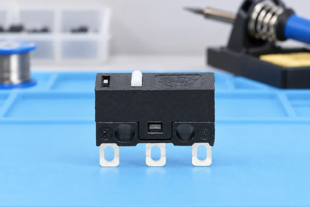
Micro switch soldering precautions should start with the exact terminal variant and its approved assembly limits. Control the heat delivered to the joint, the time and distance over which that heat reaches the housing, and the mechanical force applied while the terminal is hot. A satisfactory-looking joint does not prove that the switch mechanism or insulation escaped damage. There is no universal iron temperature or contact time that can safely be assigned to every micro switch from its operating-temperature rating. This guide addresses OEM process preparation and validation for solder terminals. The LEMA KW10-0S solder-terminal product is the illustrated example. Its product identity establishes the termination style, not a qualified soldering profile. Obtain current assembly instructions for the exact order code before releasing a production or repair procedure. KW10-0S three bare solder lugs and housing inspected beside a magnifier. Product-reference illustration, not a test result or installation drawing. Confirm that the terminal is intended for the process A switch family may offer solder lugs, PCB pins or other termination arrangements. They can have different mechanical support and assembly requirements even when the housing looks similar. Identify the complete variant and compare the terminal drawing with the intended wire, joint and fixture. A terminal hole does not by itself establish a permissible wire size or a required wrapping method. For a broader comparison, see the micro switch terminal types guide. The present article focuses on the process after a solder termination has been selected. Do not treat a solder-lug part as reflow compatible merely because it is small, or apply a PCB soldering profile to a loose wired assembly without product documentation. Ask the supplier which processes have been evaluated and...

Read More
Micro Switch Operating Speed vs Switching Frequency
Blog LEMA Electric

Micro Switch Operating Speed vs Switching Frequency

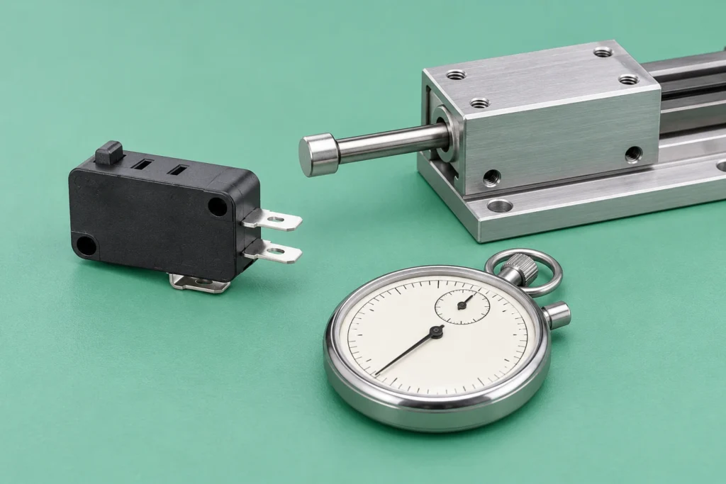
Micro switch operating speed and switching frequency describe different limits. Operating speed concerns how quickly the mechanism moves the actuator, usually expressed as a distance per unit time at a defined point. Switching frequency concerns how often a specified operating cycle can repeat. A machine can repeat slowly yet strike the actuator too quickly, or move it gently while repeating more often than the rated duty permits. Compare both with the exact contact load, travel, return motion and test conditions before approving a switch. The LEMA KW7 micro switch page lists operating speed separately from mechanical and electrical operating frequency. Use that distinction when preparing an OEM application review. The published family entry needs confirmation for the complete order code, and an abbreviated or unclear unit should be clarified with the supplier rather than silently corrected. Use the industrial micro switch selection guide to place these timing checks alongside the wider load, mounting and environmental requirements for the complete component selection.KW7 roller lever micro switch beside a separate cam specimen. Product-reference illustration, not a test result or installation drawing. Define the movement that operating speed describes A mechanism may contain several different speeds: the conveyor speed, cam surface speed, roller contact speed and plunger speed. These are related by geometry, but they are not always equal. Identify the point and direction specified by the component documentation. A quoted machine feed rate is insufficient if the actual target approaches the switch along a different path or through a lever. For a plunger switch driven directly along its intended axis, the relevant motion may be straightforward to describe. A roller lever operated by a rotating cam needs more information, including the cam...

Read More
Micro Switch Vibration and Shock Resistance: OEM Test Review
Blog LEMA Electric

Micro Switch Vibration and Shock Resistance: OEM Test Review

Micro switch vibration and shock resistance must be evaluated as both mechanical survival and electrical behavior. A switch can remain physically intact yet produce an unwanted contact transition while the equipment vibrates. Conversely, a contact that appears stable during a short observation does not establish long-term structural durability. Compare the test waveform, frequency or pulse duration, severity, direction, mounting, actuator state and monitored contact behavior before selecting a part. A single acceleration number is not enough to approve a switch for an OEM mechanism. The LEMA KW7 micro switch family page lists vibration resistance and separate shock-related entries for destruction and malfunction. Those distinctions are useful starting points for a technical inquiry. They do not establish that every variant or finished machine has passed your application's test. Obtain current documentation for the full order code and confirm the conditions behind the rating. KW7 roller lever switch beside a detached support block and loose sensor. Product-reference illustration, not a test result or installation drawing. Separate a continuous vibration exposure from a shock pulse Vibration describes oscillatory motion. A machine may expose a component to repeated excitation over a range of frequencies, and the supporting structure can affect the motion at the switch itself. Shock describes a transient event, such as a specified pulse associated with an impact. These exposures are not interchangeable, even if both are described using acceleration. Duration, repetition and the way the energy enters the assembly matter. The IEC catalogue describes IEC 60068-2-6 as a sinusoidal vibration test method and IEC 60068-2-27 as a shock test method. The methods need a relevant specification to define the exposure and acceptance conditions. Citing either standard's name without a test severity...

Read More