
Wire a micro switch only after identifying the approved terminals, intended contact state, circuit load, wire route, and isolation method. COM, NO, and NC labels describe a contact relationship; they do not by themselves prove that a component is suitable for every voltage, current, or safety function.
Part 1. What terminals does a micro switch use?
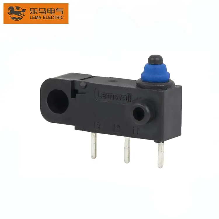
A changeover micro switch commonly has COM, NO, and NC terminals. In the free position, COM connects to one contact path; actuation transfers it to the other. Read the approved drawing and terminal marking for the exact selected model before connecting a production harness.
| Terminal field | Meaning to confirm | Assembly action |
|---|---|---|
| COM | Common contact node | Map it to the schematic reference |
| NO | Path closed after actuation | Verify the required operated state |
| NC | Path closed before actuation | Verify the required free state |
Start at the LEMA Micro Switch product line, then hold final terminal selection to the model drawing and sample.
Part 2. How do COM, NO, and NC change circuit behavior?
COM-to-NO is used when the circuit should close at the intended operating point. COM-to-NC is used when the circuit needs continuity before that point. The correct option depends on the system’s required normal state, including what the controller must see if the actuator is not engaged.
Do not infer a safe-state function from the terminal label alone. Trace the circuit through its controller input, power source, load, and any protection device.
Part 3. How should the load and contact rating be checked?
Contact rating is checked against the actual voltage, current, load type, inrush, and switching frequency. A terminal can accept a wire mechanically while the selected contact is still unsuitable for the duty.
| Load condition | Check before release | Why it matters |
|---|---|---|
| Function | Required circuit or sensing state | Prevents the wrong control behavior |
| Mechanical interface | Actuator travel or sensing geometry | Prevents missed operation |
| Electrical interface | Voltage, current, load type, controller input | Prevents contact mismatch |
| Environment | Contamination, vibration, temperature, ingress target | Sets the validation scope |
For an ingress-rated lead assembly, use the separate IP67 cable harness selection method rather than assuming an ordinary terminal connection is sealed.
Part 4. Which wiring and insulation checks matter?
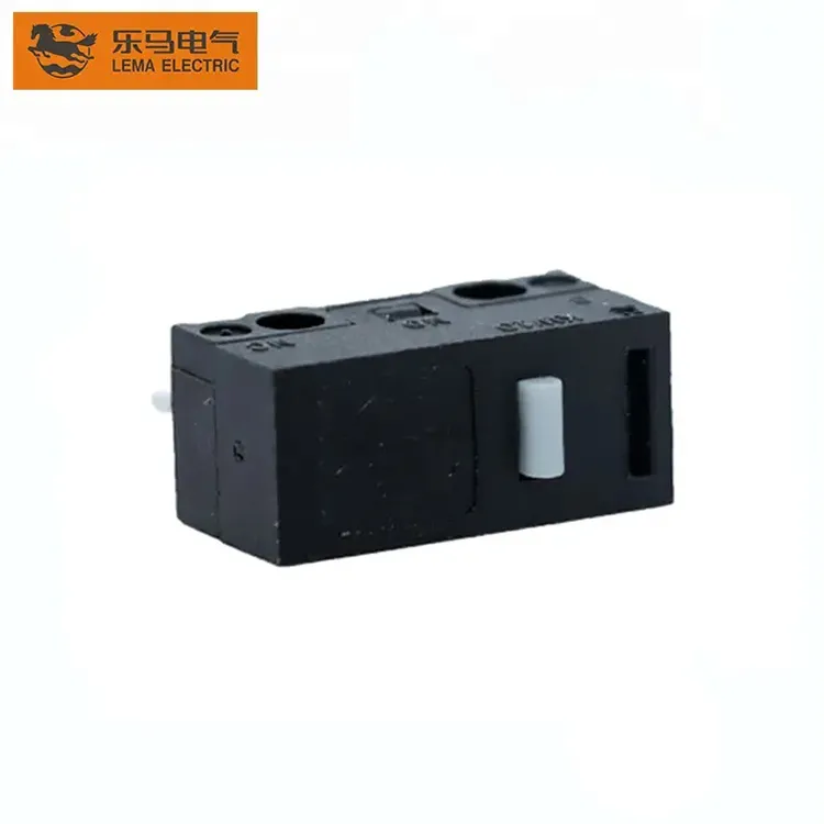
Route conductors so they do not load the actuator, abrade against a metal edge, or block service access. Provide strain relief close enough to protect the terminal, but without exceeding the supplier’s installation limits.
- Keep insulation clear of sharp edges and moving parts.
- Use the approved terminal style and crimp or solder process.
- Separate signal wiring from sources that can introduce noise where the system requires it.
- Record the harness revision with the switch model.
Part 5. How should terminals be connected in production?
Confirm terminal identity on the approved sample before releasing a work instruction. Then test continuity in both free and actuated positions, inspect conductor retention, and cycle the installed mechanism.
Production changes to wire color, terminal tooling, switch model, or routing should return to the validation plan. A similar-looking component is not an automatic substitute.
Part 6. What belongs in the wiring RFQ and Fit Boundary?
RFQ input checklist
- Schematic and required free/operated contact state
- Voltage, current, load type, and expected inrush
- Terminal style, conductor specification, and routing drawing
- Actuator travel, environment, volume, and sample timing
Fit Boundary
This guide supports an OEM wiring review. It does not certify an installation, establish a safety function, or replace model-specific ratings and validation.
Part 7. How can LEMA support a terminal inquiry?
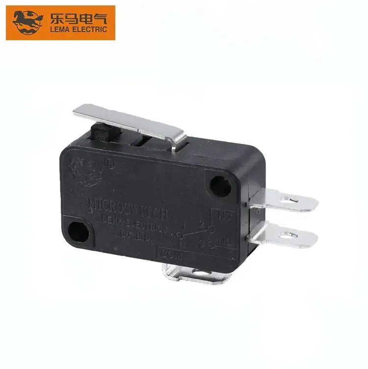
Use the KW12 series micro switch as a public starting point for a component inquiry. Share the circuit and terminal requirements so the actual model can be reviewed.
Product recommendation: contact LEMA with the approved schematic, terminal preference, load description, actuator detail, and sample plan. Do not select by terminal appearance alone.
Send an OEM switch RFQ when those inputs are ready.
FAQs
What are COM, NO, and NC on a micro switch?
COM is the common terminal. NO closes to COM at actuation, while NC opens from COM at actuation; confirm the selected model marking before wiring.
Can a micro switch be wired as normally open or normally closed?
Many changeover contact switches support either circuit path, but the drawing must state the required safe state and terminal connection.
How do I identify terminals before production?
Use the model drawing and approved sample marking, then verify continuity in both free and actuated positions.
Does a wire size determine switch suitability?
No. Select conductor and protection from the actual circuit, while also keeping the contact load inside the selected model documentation.
Can I solder directly to the terminal?
Only if the selected terminal style and supplier process allow it. Heat, lead routing, and rework limits must be validated for the model.
What should an OEM wiring RFQ include?
Provide the circuit diagram, contact state, voltage, current, load type, terminal style, wire route, environment, volume, and sample timing.