
A long handle toggle switch is not defined by one universal length. Compare the handle projection shown on the exact model drawing, then check whether the operator can reach and move it without hitting a guard, enclosure wall, neighboring control or the user’s hand. A longer lever can change hand clearance and the moment applied at the pivot, but it does not by itself prove lower actuation force or better electrical performance. Select by measured geometry, switching function and the manufacturer’s documented operating requirements.
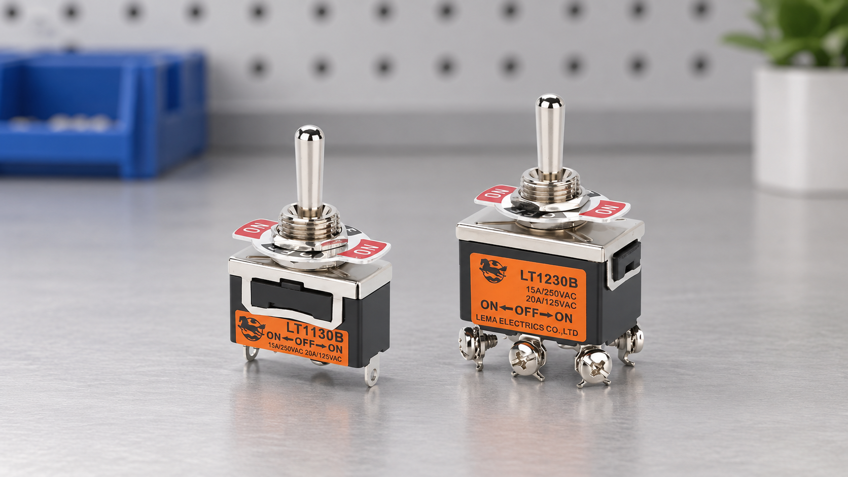
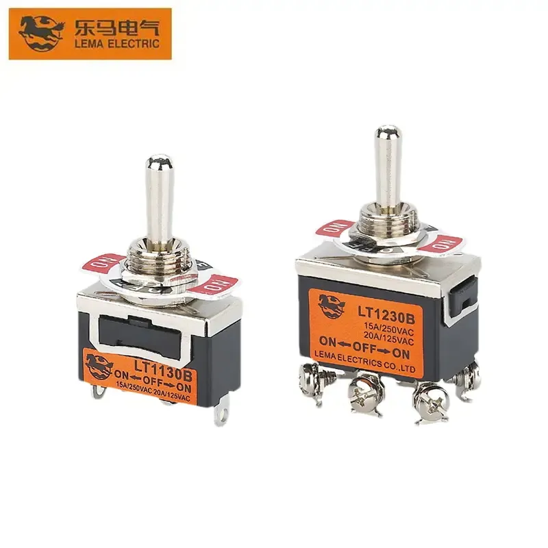
What “long handle” and “short handle” actually mean
Catalogues use terms such as bat handle, short lever, long lever, paddle or extended operator, but the wording is not a consistent measurement system across manufacturers. One supplier may describe the exposed metal lever only; another may include part of the actuator above the bushing. A web listing may also omit the drawing datum or combine several models under one title. For engineering and purchasing, replace the adjective with a dimension: record the distance from the drawing’s stated reference surface to the lever end, the panel thickness, mounting hardware and the lever’s swept envelope.
That measurement prevents a common mismatch. Two switches can both be advertised as “long handle” while one protrudes farther above the panel, has a wider lever, or travels through a different angle. Conversely, a product called “short handle” may still be the better fit when a protective cover or adjacent control limits clearance. Do not compare product photographs at different camera angles as if they were dimensioned views.
Use lever geometry carefully
For a simple rigid lever, torque magnitude is the applied force multiplied by the perpendicular distance from the pivot to the force line. In vector form, the relationship is τ = rF sin θ. This explains why moving the point where a hand pushes can change the moment at the pivot. It is useful background for comparing hand access and mechanical leverage; OpenStax’s university physics treatment of torque defines the lever arm and the role of force direction.
A complementary University of Texas physics lecture on torque describes the perpendicular lever arm and why a longer tool can produce more torque under the same applied force. Both are general physics references; the actual switch’s internal mechanism still determines its own actuation behavior.
A toggle switch is not a plain bar attached directly to the electrical contacts. Its internal spring, detent, actuator, contact carrier and stop geometry determine operating force, snap action, travel and return behavior. A longer exposed handle does not establish that the operating force falls in direct proportion to its length. Nor can it establish contact pressure, contact life or current capacity. Those values must come from the exact switch documentation or a verified test. Use the lever equation to understand user-applied moment, not to infer an undocumented switching rating.
Read the exact LEMA drawing instead of guessing from a name
The LEMA LT1 and LT2 product libraries provide separate drawings for single-pole and two-pole variants. In the currently available drawings, the indicated handle dimension is 17.0 mm for both LT1 variants, 15.5 mm for the LT2 one-pole variant and 15.4 mm for the LT2 two-pole variant. The dimension tolerance shown is ±0.2 mm. These are model-specific drawing values, not a universal definition of long and short handles and not proof that every configuration in either series is identical.
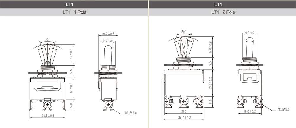
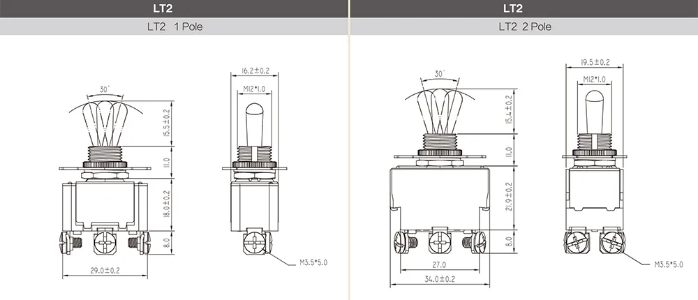
The drawings also show other dimensions that can matter more than the lever itself, including the threaded bushing, panel interface, body envelope, terminal layout and operating arc. Review the entire drawing. The LT1 and LT2 drawings display an operating arc; do not assume the lever will clear a nearby feature just because the handle-end measurement fits. A panel mock-up or a simple sweep-envelope check can expose interference before tooling or production release.
Choose by access, clearance and operator behavior
| Design question | What a longer exposed handle may change | What to verify before choosing |
|---|---|---|
| Can the operator locate the switch? | It may be easier to see or grasp when controls are recessed or gloves are worn. | Reach, visibility, glove thickness and the required direction of movement in the installed panel. |
| Is there room around the lever? | The lever may sweep through a larger space above the panel. | Guard, lid, neighboring control, wiring harness and enclosure clearance in every switch position. |
| Is accidental movement a concern? | A more exposed lever may be easier to bump or snag. | Whether a guard, recessed mounting, detent or another control architecture is required by the risk review. |
| Does the operator need a particular feel? | The hand’s point of contact changes, but internal switch force is model-dependent. | Operating force, travel, detent, return action and sample evaluation from the actual manufacturer variant. |
| Will a substitute fit the panel? | Handle length alone does not predict fit or wiring compatibility. | Bushing thread, panel thickness, body size, terminal type, contact form and dimensional drawing. |
This is a qualitative screening table, not a claim that every longer handle has the same feel or safety consequence. If controls are used in a hazardous machine, handle shape is only one part of the interface. A cover can reduce some accidental contact, but it does not create a safety-rated function. Follow the equipment risk assessment, applicable standards and machine-builder requirements for the complete control.
Check the complete movement envelope
Measure from the panel surface to the nearest obstruction, then compare that clearance with the switch’s drawing and the lever’s operating arc. Include the lever tip, any boot or cap, panel bevel, door or removable cover, and a practical allowance for installation tolerance. Check access from the operator’s real approach direction, not only from a front elevation. A switch mounted near a door edge may have ample static clearance but collide with the door as it closes.
When the drawing does not show every required clearance, ask the supplier for a controlled drawing or test the actual sample in a panel coupon. Do not scale a screenshot. If a product has a boot, nut, washer or optional guard, verify whether the supplied dimensions include it. Record the part number, drawing revision and measurement datum in the release file so future sourcing does not quietly substitute a different operator length.
Validate operating force and travel on the selected model
Panel geometry cannot replace an operating-force check. For an ergonomic review, define where and how the operator will push, the required switching direction, the user’s access, expected repetitions and any gloves or protective equipment. Then obtain the manufacturer’s operating-force and travel specification for the exact model or evaluate representative samples using a documented method. A pull gauge or force fixture can help compare samples when the measurement point and direction are kept constant, but a sample result does not automatically become a guaranteed production limit.
Also check the electrical function independently: number of poles, circuit arrangement, maintained or momentary behavior, terminal style and voltage/current rating. A lever that feels right but has the wrong contact arrangement is not a suitable replacement. If a toggle controls a low-voltage input, verify input compatibility; if it switches a load, use the model’s load-specific rating and the machine’s protective design. Mechanical appearance is not an electrical specification.
Use a repeatable selection and RFQ checklist
- State the control task and required maintained, momentary or center-return behavior.
- Give the exact panel thickness, mounting-thread requirement, cutout and available body depth.
- Define the handle measurement datum and required projection, then attach the panel envelope or drawing.
- List obstructions, neighboring controls, guarding, gloves, operator approach and expected use frequency.
- Specify contact arrangement, terminal type, electrical load and any documented environmental requirement.
- Request the current drawing and operating specifications for the exact order code; confirm whether options change the dimensions.
- Evaluate a production-intent sample if hand feel, clearance or duty is critical, and record the model and test setup.
For LEMA options, compare the LT1 series toggle switch and the LT2 series toggle switch by their model drawings, not by series names alone. The toggle-switch mechanism guide explains actuator and contact behavior. For installation geometry, see the toggle-switch hole-size guide and the panel-mount toggle-switch guide. Where unintended movement is a concern, review the separate toggle-switch guard guide and the machine-level risk requirements.
Why torque is helpful—and where the analogy stops
The video below is a neutral Khan Academy lesson on torque. It helps visualize the relationship between a pivot, a force and its perpendicular lever arm. The example is general physics, not a toggle-switch test and not a specification for any LEMA product. Use it to understand geometry, then return to the exact manufacturer’s drawing and operating data for selection.

Watch Torque | Physics on YouTube. The lesson is general education; the actual toggle mechanism may include internal springs and detents that change the hand force and travel.
Frequently asked questions
Is there a standard length that makes a toggle switch “long handle”?
No universal threshold applies across manufacturers. Compare the dimension from each product drawing and its stated datum, then record the exact model and variant.
Will a longer toggle lever always require less hand force?
No. Lever geometry changes the applied moment, but the switch’s internal mechanism, detent, spring and required movement also determine operating force. Use the exact model specification or evaluate a sample.
Can I substitute an LT1 handle for an LT2 handle?
Do not assume the series are interchangeable from appearance alone. Confirm the full model, mounting dimensions, contact arrangement, terminal style, ratings and current drawing with the supplier.
What should I check when a switch is behind a guard or enclosure door?
Check the complete lever sweep and tip clearance in every position, including the guard, boot, door movement, wiring and assembly tolerances. Validate the real panel arrangement before release.