CENTRE D’ACTUALITÉS LEMA

Actualités et blog

Centre d’actualités

Guide de câblage d’un interrupteur à bascule DPDT à inversion de polarité
Blogue LEMA Électrique

Guide de câblage d’un interrupteur à bascule DPDT à inversion de polarité

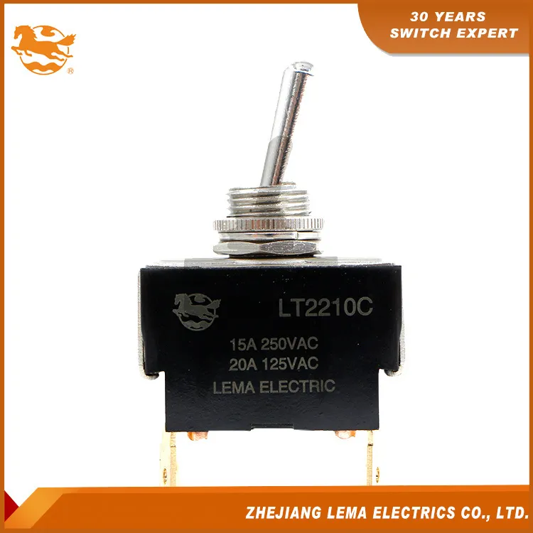
Un commutateur à bascule DPDT peut inverser la polarité appliquée à un moteur à courant continu (CC) à aimants permanents et à deux fils en permutant simultanément les deux connexions du moteur. Dans une configuration courante à six bornes, connectez le moteur aux deux bornes communes centrales et disposez les alimentations positive et négative sur deux coins extérieurs opposés, de sorte que les deux positions du commutateur inversent la polarité. La disposition des bornes n'est pas universelle : identifiez les bornes communes et les bornes de commutation à partir du schéma exact du commutateur ou à l'aide d'un multimètre en mode continuité avant d'effectuer le câblage. Il s'agit d'une explication de la topologie du circuit, et non d'une validation de la commutation directe d'un moteur particulier. Le courant de démarrage et le courant de blocage d'un moteur CC peuvent être beaucoup plus élevés que son courant de fonctionnement normal, et un moteur constitue une charge inductive. Les informations produit du LEMA LT2210C présentées dans cet exemple indiquent des caractéristiques nominales en courant alternatif (CA) ; elles ne permettent pas d'établir une capacité nominale de commutation d'un moteur CC. Pour l'utilisation réelle du moteur, utilisez un composant DPDT disposant d'une valeur nominale en courant continu publiée, ou un relais/contacteur correctement dimensionné ou un pilote de moteur. Image réelle du produit LT2210C. Elle montre un produit DPDT à trois positions ; vérifiez séparément le schéma de câblage exact et la valeur nominale de la charge en courant continu. Signification de DPDT dans un circuit d'inversion de polarité. DPDT signifie double pôle, double direction : le commutateur commande deux circuits distincts, et chaque pôle peut relier sa borne commune à l'une de deux bornes de commutation. Dans un circuit d'inversion de polarité, les deux pôles permutent simultanément les deux fils du moteur. Dans une position du commutateur, le positif est appliqué au fil A du moteur et le négatif au fil B ; dans l'autre position, ces connexions sont inversées. L'inversion de la polarité de la tension aux bornes d'un moteur CC à balais et à aimants permanents inverse son sens de rotation, comme l'explique le guide de SparkFun consacré aux moteurs CC à balais. Un commutateur portant le marquage ON-OFF-ON possède une troisième position centrale, qui déconnecte les deux pôles. Cette configuration est souvent utile pour une commande manuelle...

Lire la suite
Valeurs nominales des contacts des fins de course en CA et CC : guide de sélection
Blogue LEMA Électrique

Valeurs nominales des contacts des fins de course en CA et CC : guide de sélection

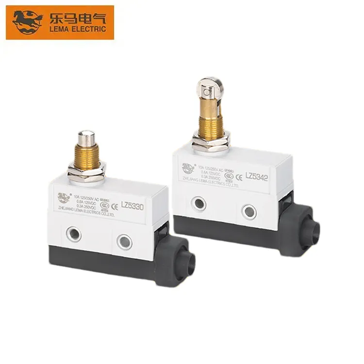
Un fin de course ne possède pas une intensité nominale universelle. La charge admissible dépend du modèle exact, de la tension, de l’alimentation CA ou CC, du type de charge, de la fréquence de commutation et des conditions d’essai définies par le fabricant. Une valeur nominale de contact en CA ne peut pas être transposée en CC en utilisant la même intensité ou en convertissant les watts. Avant de raccorder une charge réelle, vérifiez les caractéristiques nominales indiquées pour le bloc de contacts spécifique et l’application prévue. Ce guide explique comment interpréter les caractéristiques nominales des contacts en CA/CC et présente un exemple avec le LEMA LZ5. Il ne constitue pas une approbation générale pour toutes les configurations du LZ5 : avant la validation de la conception, confirmez auprès du fournisseur le code de commande, la révision de la fiche technique, le type de bornes, les conditions environnementales et la charge réelle. Référence du produit LZ5 réel. L’actionneur et le boîtier illustrés permettent d’identifier la famille de produits, mais ne définissent pas les limites électriques de chaque variante. Ce qu’indique une caractéristique nominale de contact — et ce qu’elle n’indique pas Une valeur nominale constitue une limite établie dans des conditions d’essai spécifiées, et non une garantie que toute charge inférieure à l’intensité indiquée fonctionnera pendant la durée de vie requise. Lisez l’ensemble des caractéristiques : tension, intensité, CA ou CC, ainsi que toute catégorie de charge ou condition relative au facteur de puissance ou à la constante de temps. Vérifiez également si la valeur concerne le courant d’établissement, le courant de maintien ou le courant de coupure d’une charge. Ces contraintes ne sont pas interchangeables. Dans une machine, un fin de course sert souvent à détecter une position et à envoyer un signal à un automate programmable (API) ou à un relais, plutôt qu’à alimenter directement un moteur. Une entrée d’API constitue généralement une charge de commande à faible énergie ; une bobine de contacteur est une charge inductive ; et un moteur présente un courant d’appel élevé. Un même contact de commutateur peut donc subir des contraintes très différentes selon le cas d’utilisation. Si le commutateur sert uniquement à signaler une position, une entrée de commande correctement conçue ou un relais d’interface peut permettre de préserver le contact du commutateur des contraintes liées à la puissance...

Lire la suite
Micro-interrupteur pour montage sur circuit imprimé : empreinte, soudage et actionnement
Blogue LEMA Électrique

Micro-interrupteur pour montage sur circuit imprimé : empreinte, soudage et actionnement

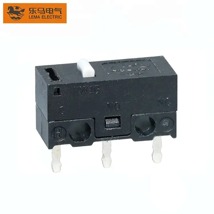
Un micro-interrupteur à montage sur circuit imprimé (PCB) n’est pas un composant générique à trois broches doté d’une empreinte universelle. Avant de concevoir les pistes de cuivre, identifiez la variante exacte des bornes, vérifiez le plan du fabricant, repérez les bornes COM/NO/NC et prévoyez suffisamment d’espace pour l’actionneur et sa course complète. Pour une conception OEM, l’empreinte du circuit imprimé, le support mécanique, le procédé de soudage et les contraintes électriques doivent être vérifiés conjointement. Ce guide utilise le LEMA KW10-0P comme exemple spécifique de produit. Il s’agit d’un petit interrupteur à action brusque doté de bornes droites pour circuit imprimé ; cette famille illustre également l’importance des suffixes indiquant le type de bornes. Ne reproduisez pas l’empreinte ou le profil de soudage d’une autre variante KW10 sans vérifier leur correspondance avec le plan exact et la spécification contrôlée. Référence du produit KW10-0P réel : vérifiez le type de bornes et l’orientation du boîtier par rapport à la référence de pièce sélectionnée. Qu’est-ce qui rend un micro-interrupteur compatible avec un montage sur circuit imprimé ? Un interrupteur destiné au montage sur circuit imprimé possède une géométrie de bornes conçue pour être insérée dans un circuit imprimé ou raccordée à celui-ci. Cette seule description ne permet pas de déterminer si le composant est destiné à un montage traversant, quelle partie de la borne doit être soudée, si le corps de l’interrupteur nécessite un support supplémentaire ni quelles dimensions de perçage utiliser pour le circuit imprimé. Les familles de produits peuvent proposer des broches droites pour circuit imprimé, des broches autobloquantes, des cosses à souder, des languettes à connexion rapide et des bornes pour fils. Il s’agit d’interfaces distinctes, et non de différentes appellations désignant une même empreinte. Par exemple, l’image de référence des bornes du KW10 distingue les bornes droites pour circuit imprimé, une borne autobloquante pour circuit imprimé et une borne à souder. Le suffixe et le plan exact déterminent le type de borne fourni. Une broche droite peut dépendre du circuit imprimé et du dispositif de fixation pour maintenir son alignement pendant l’assemblage ; une version autobloquante peut présenter une forme de broche différente. Aucun de ces types ne doit être déduit de la seule photographie de la partie supérieure de l’interrupteur. Commencez par consulter le plan, et non par vous fier à une...

Lire la suite
Module d’alimentation secteur intégré ou prise d’entrée, interrupteur et fusible séparés
Blogue LEMA Électrique

Module d’alimentation secteur intégré ou prise d’entrée, interrupteur et fusible séparés

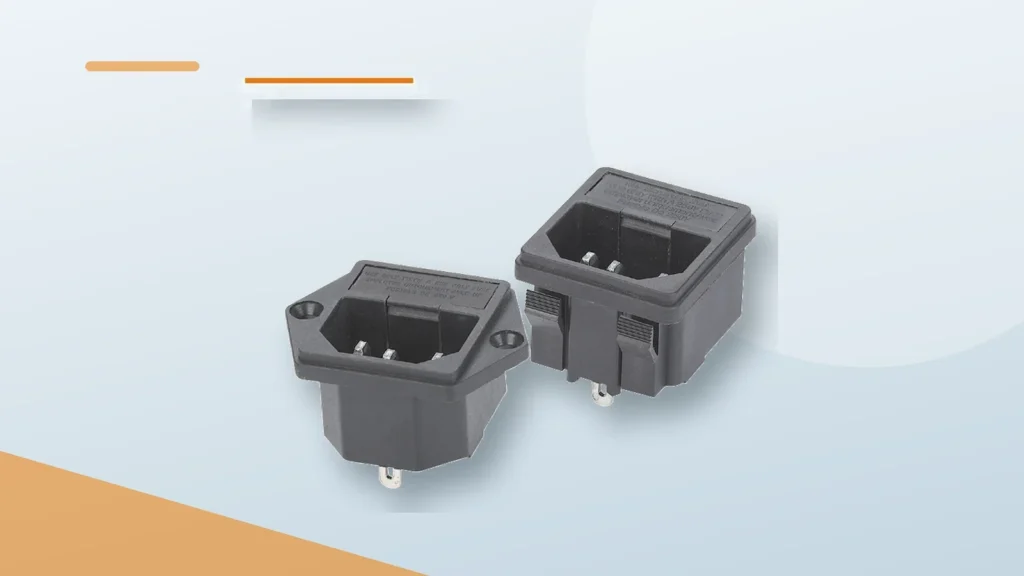
A power entry module combines two or more mains-entry functions—typically an appliance inlet with a switch, fuse holder or filter—into one panel assembly, while a separate-component design uses individual parts and wiring. The module can save panel space, reduce part count and simplify assembly. Separate components provide more freedom for ratings, service access, heat spacing and supplier choices. The better architecture depends on safety approvals, fuse strategy, EMC needs, panel constraints, production volume and maintenance. This guide compares the choices for OEM equipment. LEMA IPZ-series images are real inlet references; the photographed variants do not establish that every function is integrated. Confirm the exact model and schematic. Comparison table Decision factorIntegrated power entry moduleSeparate inlet, switch and fuseVerify Panel spaceCompact shared cutoutMore distributed areaCutouts, clearances and rear depth AssemblyFewer panel parts and jumpersMore wiring and hardwareWork instructions and inspection points FlexibilityFunctions tied to one modelEach component selected independentlyRatings, poles, fuse and filter options ServiceOne module may be replaced as a unitSingle failed part can be changedAccess, spares and fuse replacement ApprovalsModule evidence can simplify component reviewEach part and assembly relationship reviewedExact certifications and end-product conditions Supply riskGreater dependence on one combined itemMore approved alternatives possibleSecond sources and change control What counts as a power entry module A basic appliance inlet only provides the detachable power connection. A power entry module integrates additional functions in the same housing or coordinated assembly. Possible elements include a line switch, one or two fuse positions, voltage selector and electromagnetic-interference filter. Product naming varies, so the schematic and bill of materials should identify the actual functions. Do not assume a rectangular inlet contains a fuse because a drawer-like feature is visible. Likewise, a fused inlet...

Lire la suite
Bouton-poussoir coup de poing : utilisations et critères de sélection
Blogue LEMA Électrique

Bouton-poussoir coup de poing : utilisations et critères de sélection

A mushroom push button switch uses a wide, prominent actuator that is easy to locate and press, but head shape alone does not make it an emergency-stop device. Select it by intended command, maintained or momentary action, contact arrangement, color, legend, panel fit, electrical duty and required safety function. A general machine-control button and a compliant emergency-stop operator may look similar while having different latching, reset, contact and certification requirements. This guide separates those uses and provides an OEM selection process. LEMA PBS-series photos are real product references for a domed push-button form; confirm the exact model drawing and approvals before specifying any safety-related function. Selection table DecisionGeneral mushroom buttonEmergency-stop applicationEvidence required PurposeLarge manual commandStop hazardous motion in defined conditionsMachine risk assessment and control narrative ActionMomentary or maintainedTypically latching with deliberate resetExact mechanical action and reset method ContactsNO, NC or changeover as requiredSafety architecture may require specific NC/direct-opening contactsContact diagram and compliance documentation Color/markingChosen for machine conventionGoverned by applicable standards and project rulesPanel design and standard review ValidationFunctional and endurance checksComplete safety-function validationTest plan and recorded results Why the large head is useful A broad actuator is easier to find with a hand, glove or palm than a small flush button. It can suit start, stop, acknowledge, cycle request or other commands where visibility and a generous target area are valuable. The shape can also reduce the precision needed for actuation. That advantage creates a trade-off: a projecting head may be struck accidentally. Consider guards, shrouds, spacing and panel location according to the command. A guard must not make an intended urgent action difficult. Test the layout with representative operators, gloves, lighting and viewing angles. LEMA PBS-series product reference showing...

Lire la suite
Indices de protection IP des pédales à pied pour les environnements de travail humides et poussiéreux
Blogue LEMA Électrique

Indices de protection IP des pédales à pied pour les environnements de travail humides et poussiéreux

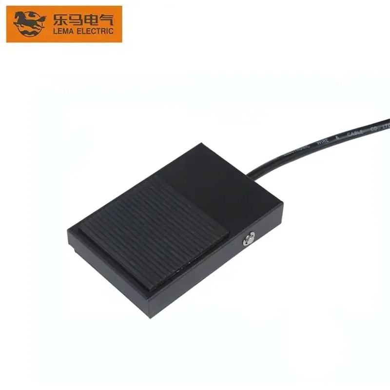
A waterproof foot switch should be chosen from the complete installed system, not from a product photo or the word “waterproof.” The relevant IP rating applies only to the exact tested enclosure, cable entry, connector and operating condition. Water jets, standing water, metal dust, oil, washdown chemicals and outdoor condensation are different exposures. Define the contaminants and cleaning method first, then verify the switch’s documented IP code, mounting position, cable termination and maintenance plan. This guide explains how to specify a foot control for wet and dusty work areas. LEMA LF-series images provide real product references, but no rating is inferred from appearance. Ask for the controlled datasheet and test evidence for the exact model. IP rating decisions at a glance Environment questionWhy it mattersEvidence to requestCommon mistake Dust type and quantityFine conductive dust differs from coarse dry debrisExact first IP digit and test scopeCalling any covered pedal dustproof Water sourceDrips, spray, jets and immersion are separate testsSecond IP digit, orientation and durationTreating all water exposure as equivalent Cable exitIngress often begins at the gland or connectorCable diameter range and assembly instructionRating the pedal but not the cable assembly Cleaning chemicalsCompatibility is not defined by IP aloneMaterial and chemical-resistance confirmationAssuming washdown detergent is harmless Mechanical damageCracks and impacts defeat sealsInspection criteria and replacement limitsKeeping a damaged enclosure in service What the two IP digits mean The first digit describes protection against access to hazardous parts and solid foreign objects. The second describes protection against water under specified laboratory conditions. Higher digits are not a universal promise for every contaminant, pressure, chemical or installation. The IEC explanation of IP ratings provides the official framework; purchase decisions should use the applicable IEC...

Lire la suite
Utilisations des circuits ON-OFF-ON d’un commutateur à bascule à position centrale arrêt
Blogue LEMA Électrique

Utilisations des circuits ON-OFF-ON d’un commutateur à bascule à position centrale arrêt

A center-off toggle switch has three stable lever positions—ON, OFF and ON—so the middle position disconnects the controlled path while either outer position selects a different circuit state. It is commonly used for forward/stop/reverse requests, raise/stop/lower controls, source selection and manual mode commands. The label describes lever behavior, not the internal terminal map. Pole count, maintained or momentary action, contact sequence, voltage, load and interlocking must all be verified before wiring. This guide explains how to specify an ON-OFF-ON switch without confusing it with ON-ON-ON or momentary variants. LEMA LT3130A images are real product references. Always use the exact model drawing and continuity table for the selected ordering code. Center-off patterns compared MarkingCenter stateOuter positionsTypical use ON-OFF-ONMaintained open/neutral stateTwo maintained selectionsDirection or source selection with a stop position (ON)-OFF-(ON)Maintained centerMomentary both sidesRaise/lower or jog commands (ON)-OFF-ONMaintained centerOne momentary, one maintainedMixed command functions after risk review ON-ON-ONConnected center patternTwo additional connected patternsMulti-circuit selection; not center-off ON-OFFNo third positionOne connected, one disconnectedSimple two-position control Parentheses conventionally indicate spring-return positions, but markings vary. Confirm the mechanical action and circuit diagram instead of ordering from punctuation alone. What happens in the center position In a true center-off function, the relevant moving contact is not connected to either outer throw in the center position. In a single-pole version, a common terminal usually selects one of two throws. In a double-pole version, two independent commons change together. The center may disconnect both poles, but terminal numbering and physical layout differ between families. Center-off does not guarantee galvanic isolation for every circuit or a safety-rated stop. Contact spacing, leakage through other components, shared commons and downstream electronics still matter. If isolation or hazardous-motion stopping is required, use...

Lire la suite
Guide de montage des interrupteurs de fin de course : position et répétabilité
Blogue LEMA Électrique

Guide de montage des interrupteurs de fin de course : position et répétabilité

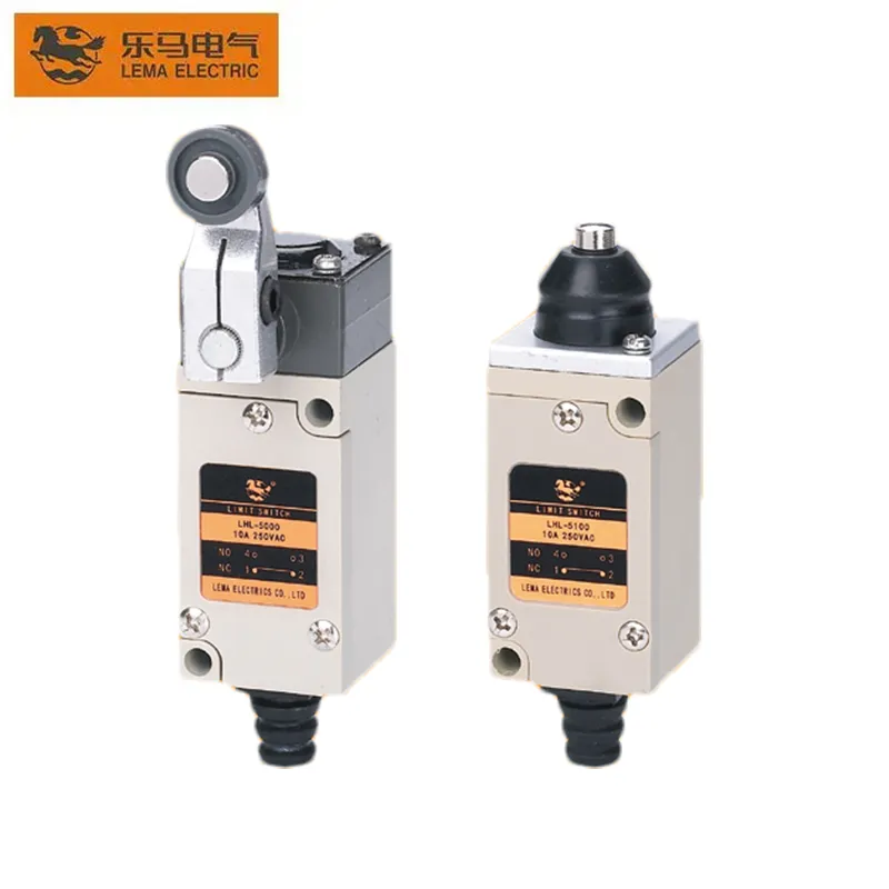
Correct limit switch mounting places the actuator where the machine target reaches the operating point consistently, travels far enough to create margin, and stops before the switch is mechanically overloaded. Repeatability depends on the complete system: bracket stiffness, target geometry, approach direction, speed, actuator type, bearing play, temperature, contamination and electrical response. A precise switch on a flexible bracket will not produce a precise machine reference. This guide gives an OEM mounting and validation process using LEMA HL-series products as real visual references. Product photos show the physical family only. Confirm the exact operating position, movement differential, overtravel, allowable force, approach angle and enclosure data from the controlled model drawing. Mounting decisions at a glance DecisionPreferred practiceRisk if ignoredVerification BracketRigid, located by repeatable datumsPosition drift and vibrationDeflection check and torque record ApproachFollow permitted actuator directionSide load, impact or lever damageSlow-motion observation Operating marginTarget passes operating point without exceeding limitIntermittent actuation or overtravelWorst-case tolerance test Target surfaceSmooth, durable and correctly profiledWear, bounce and inconsistent releaseInspection after cycling CableSupported with strain relief and service loopTerminal load or water pathPull and routing inspection Machine referenceDefined independently of switch housingUncontrolled calibration changesGauge or fixture measurement Define what “repeatability” means Repeatability is the spread of switching positions when the same mechanism approaches under the same conditions. It is not the same as absolute accuracy. A switch can repeat closely but actuate at an offset from the desired machine coordinate. A system may also change with approach direction because mechanical backlash, lever friction and movement differential create hysteresis. Write an acceptance statement with units and test conditions. For example: “input changes state within the approved position band during ten forward approaches at production speed and releases...

Lire la suite
Micro-interrupteur pour charges inductives : guide des caractéristiques nominales et de la protection
Blogue LEMA Électrique

Micro-interrupteur pour charges inductives : guide des caractéristiques nominales et de la protection

A micro switch for an inductive load must be selected from the load’s making and breaking behavior, not from a resistive current number alone. Solenoids, relays, contactors and small motors can draw inrush current and create a voltage spike when the circuit opens. Those effects can erode or weld contacts, produce electrical noise and shorten service life. The safe method is to identify the actual load, check the exact switch rating for that load category, keep margin, and use a suitable suppression or interface device when the switch data does not directly cover the duty. This guide explains the engineering questions behind that choice. LEMA KW12-series images are used as real product references, but the photographed appearance does not prove a particular inductive-load rating. Confirm the ordering code, datasheet, circuit voltage, current, operating rate and environmental conditions before approval. Why an inductive load is harder on contacts An energized coil stores energy in its magnetic field. When a mechanical contact opens, current tries to continue flowing. The resulting voltage across the opening gap can create an arc. At closing, a motor or transformer may also draw a current higher than its steady-state value. A switch that carries a small resistive heater current comfortably can therefore fail early when used at the same nameplate current with a coil or motor. The problem is not solved by looking only at watts. AC and DC arcs behave differently, coil time constants differ, and the contact material, gap, speed and enclosure all affect interruption. Treat “inductive” as a prompt to obtain the exact switching category and test conditions rather than as a universal derating percentage. Selection table for common inductive duties LoadMain stressInformation requiredTypical...

Lire la suite
AC Power Inlet Fuse Sizing for OEM Equipment
Blogue LEMA Électrique

AC Power Inlet Fuse Sizing for OEM Equipment

An AC power inlet fuse cannot be selected from the inlet current rating or appliance wattage alone. Start with the equipment’s maximum steady input current at the lowest permitted supply voltage, then evaluate startup inrush, abnormal-load behavior, conductor capacity, fuse time-current curve, voltage rating, breaking capacity, ambient temperature, holder rating and applicable equipment standard. The selected fuse must carry normal operation without nuisance opening while interrupting defined faults safely. A licensed or otherwise qualified designer must confirm the final protective scheme. This guide provides an OEM selection process for a fused AC inlet. It does not prescribe a universal multiplier or a fuse value for a specific machine. LEMA IPZ-series images are product references only; the exact inlet, fuse holder and fuse must be checked as a coordinated assembly. Inputs required before choosing a fuse Design inputWhy it mattersEvidence to collect Supply voltage and frequency rangeChanges operating current and must remain within fuse voltage ratingEquipment input specification Maximum steady input currentEstablishes the normal thermal loadWorst-case measurement and calculation Startup or inrush waveformMay open a fast fuse despite acceptable steady currentPeak current, duration, repetition and temperature Fault current availableMust not exceed the fuse’s interrupting capabilityInstallation or supply-system study Internal conductor and component limitsThe fuse must protect the intended weak pointsWire, PCB, switch, filter and load ratings Ambient and enclosure temperatureChanges fuse carrying capacity and holder heatingWorst-case thermal test Applicable standard and approvalDefines construction, spacing, testing and replacement markingCompliance plan and certified component records If any of these inputs is unknown, the correct action is to measure or obtain it, not to increase the fuse rating until nuisance opening stops. An oversized fuse may leave the cord, inlet, switch, filter or internal...

Lire la suite
Push Button Switch Symbols: NO, NC and Illuminated Types
Blogue LEMA Électrique

Push Button Switch Symbols: NO, NC and Illuminated Types

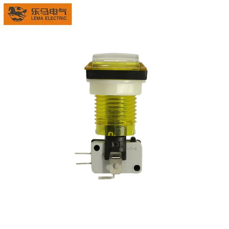
A push button switch symbol combines two separate ideas: the actuator that a person presses and the electrical contact state that changes. Read the contact in its normal, unactuated and de-energized condition unless the drawing states otherwise. A normally open contact is open at rest and closes when actuated; a normally closed contact is closed at rest and opens when actuated. An illuminated push button also has a lamp or LED circuit, which must be shown and wired separately from the contact circuit. This guide explains how engineers, panel builders and buyers should interpret NO, NC, changeover, maintained, momentary and illuminated push-button symbols. It does not replace the symbol legend, applicable drawing standard or terminal diagram for the exact product. Common push-button symbol meanings Drawing elementMeaning at normal stateChange when pressedTypical verification NO make contactCurrent path is openContact closesCOM–NO continuity appears NC break contactCurrent path is closedContact opensCOM–NC continuity disappears Changeover contactCOM is connected to NCCOM transfers to NOMeter both paths in both states Momentary actuatorReturns when releasedOperates only while force is appliedRelease test through full travel Maintained actuatorRemains in selected stateRequires another action to resetOperate and reset according to drawing Lamp or LEDIndependent indicator circuitIlluminates when its supply is presentCheck rated voltage and LED polarity Graphic details vary among IEC, ANSI and company-specific drawing systems. The project legend governs the drawing. The functional questions remain the same: what is the normal state, what mechanical action causes transfer, which terminals belong to each contact, and what returns the device to normal? LEMA PBS-001 product reference. A product photograph shows construction, while the schematic symbol and terminal drawing define electrical behavior. NO and NC: functional contact sketchesContactAt restWhile actuatedNO — normally...

Lire la suite
Single-Pedal vs Dual-Pedal Foot Switch
Blogue LEMA Électrique

Single-Pedal vs Dual-Pedal Foot Switch

A single-pedal foot switch is usually the clearer choice when an operator needs one deliberate command. A dual-pedal foot switch is appropriate when two distinct commands must remain available at the same workstation, such as raise/lower or clamp/release. Pedal count alone does not make either design safer. The machine risk assessment, control logic, guarding, pedal spacing, operating force, cable arrangement and validation determine whether the selected control is suitable. For purchasing, define what each pedal must do in every machine state before choosing the enclosure. This guide compares single- and dual-pedal layouts for industrial and OEM equipment. It uses LEMA LF-series product shapes as real construction references, but it does not assign an unverified safety function, ingress rating or electrical rating to a photographed model. Always confirm the exact ordering code, drawing and test record. Single pedal versus dual pedal at a glance Decision pointSingle pedalDual pedalWhat to verify Number of commandsOne command or one hold-to-run functionTwo clearly separated commandsMachine operating narrative and I/O list Operator choiceLower selection burdenRequires reliable left/right or front/rear identificationPedal spacing, labels and usability trial Control contactsOne contact set or one control channelIndependent contacts or circuits may be requiredExact schematic and continuity test Cable and connectorUsually fewer conductorsMay need separate returns, commons or connector pinsHarness drawing and connector pinout Failure analysisOne actuator to diagnoseCross-wiring and command confusion must be consideredFMEA, commissioning and fault tests Best fitStart, jog, enable or one-direction requestTwo-direction or two-stage operator requestsApplication-specific risk assessment A dual pedal should not be selected merely because it leaves room for future functions. An unused pedal can still be pressed, misunderstood or wired incorrectly. If the equipment only needs one command, a single pedal normally makes the...

Lire la suite