CENTRE D’ACTUALITÉS LEMA

Actualités et blog

Centre d’actualités

ON-ON-ON Toggle Switch: Circuit Logic and Wiring
Blogue LEMA Électrique

ON-ON-ON Toggle Switch: Circuit Logic and Wiring

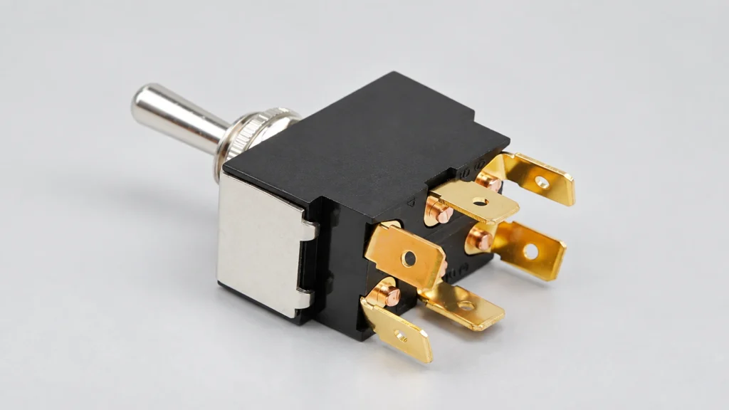
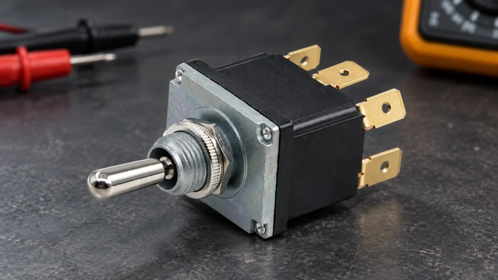
An ON-ON-ON toggle switch is a three-position selector with an active contact combination in all three lever positions. In the common DPDT six-terminal version, the two poles do not necessarily transfer in the same way at the center position: one pole may connect toward one end while the other connects toward the opposite end. That staggered center logic is what makes series/split/parallel and other three-mode circuits possible. Never wire it from an ON-OFF-ON diagram; identify every continuity pair on the exact switch first. This guide explains ON-ON-ON toggle switch logic, terminal mapping, bench testing and OEM selection. LEMA product photos illustrate the physical DPDT toggle form and six-terminal layout. The referenced LT3230C listing is ON-OFF-ON, so its exterior photograph must not be treated as proof of ON-ON-ON internal contacts. ON-ON-ON is a contact sequence, not an appearance Three-position toggles can share the same lever, bushing and terminal footprint while having different internal sequences. ON-OFF-ON opens both poles in the center. ON-ON uses two maintained positions. Momentary functions are shown with parentheses, such as (ON)-OFF-(ON). ON-ON-ON maintains a defined connection in every position. The ordering code and contact table, not the number of detents or terminals, distinguish them. MarkingLever positionsCenter behaviorDo not assumeON-ONTwo maintainedNo center detentNot a three-mode selectorON-OFF-ONThree maintained or mixedBoth poles normally openCenter is not an active routeON-ON-ONThree maintainedStaggered or defined active contactsCenter pattern is not universal(ON)-OFF-(ON)Momentary endsOpen centerLever does not stay at the ends Some suppliers publish more than one ON-ON-ON center-contact pattern. A guitar-wiring source may call them Type I and Type II; industrial datasheets may use a contact truth table. Both descriptions mean the assembler must verify the exact variant. A familiar six-lug drawing from another...

Lire la suite
IEC C20 Inlet vs C14 Inlet for Equipment Power
Blogue LEMA Électrique

IEC C20 Inlet vs C14 Inlet for Equipment Power

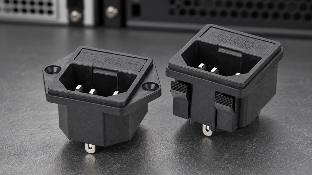
IEC C14 and C20 are grounded appliance inlets from the IEC 60320 family, but they are different interfaces and are not interchangeable. C14 mates with a C13 cord connector; C20 mates with a C19 connector. C20 is the larger choice used when the equipment input current exceeds what an approved C14 implementation can provide. The final rating is never selected by shape alone: check the exact inlet, cord set, fuse, wiring, terminal, ambient temperature, approvals and destination-market rules as one power-entry system. This C20 vs C14 inlet comparison is for OEM equipment design. LEMA’s current product-image library provides a C14-style IPZ inlet reference, so the photographs below deliberately do not claim to show a LEMA C20 product. Connector identities and mating pairs The equipment-side male appliance inlet is designated C14 or C20; the cord-side female connector is C13 or C19 respectively. The different outlines help prevent an unintended mating combination. IEC 60320-1 sets general appliance-coupler requirements, while IEC 60320-3 contains the standard sheets and gauges that define dimensional compatibility. The current IEC 60320-1 publication applies to appliance couplers integrated into equipment, and IEC 60320-3 covers the standard dimensions. Decision pointC14 inletC20 inletOEM actionMating cord connectorC13C19Specify both inlet and approved cord setPhysical interfaceSmaller standard-sheet geometryLarger, differently keyed geometryUse the exact manufacturer cutout drawingCurrent classCommon lower-current equipment inputHigher-current IEC 60320 optionUse the marked/approved rating for market and temperatureTypical system impactSmaller cutout and cord ecosystemLarger inlet, cord and conductor requirementsReview fuse, terminals, wire gauge and thermal rise togetherDirect substitutionNo; connector, cutout and cord set differRequalify the complete power-entry design A common shorthand describes C14 as a 10 A international interface and C20 as a 16 A international interface, with different approved values possible...

Lire la suite
5-Pin Push Button Switch Wiring With LED
Blogue LEMA Électrique

5-Pin Push Button Switch Wiring With LED

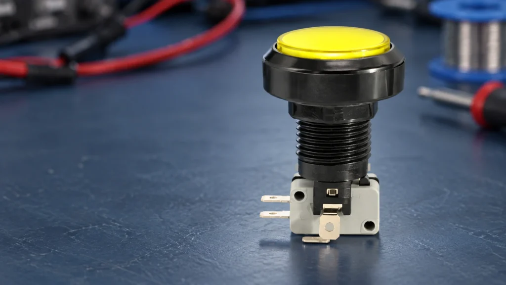
A typical 5-pin illuminated push button contains two electrically separate parts: a three-terminal changeover switch marked COM, NO and NC, plus two lamp terminals. Wire and test those parts independently. With power isolated, identify COM–NO and COM–NC by continuity; then confirm the lamp’s rated voltage and, for an LED, its polarity. Do not copy a color code or terminal position from another brand. The exact LEMA drawing and markings for the selected PBS variant must control the final connection. This guide explains the logic behind a 5-pin push button switch wiring diagram without presenting one terminal layout as universal. It covers momentary control, constant and switched illumination, PLC inputs, commissioning and the information an OEM should place on its drawing. Separate the contact circuit from the light circuit The contact section is normally an SPDT changeover contact. COM is the moving common. At rest, COM is connected to NC and isolated from NO. When the mechanism is fully actuated, COM connects to NO and leaves NC. The two remaining terminals supply the lamp. Their voltage is not automatically the same as the load circuit, and an LED normally requires the specified polarity. Some illuminated devices include current limiting for a declared supply; others require an external circuit. Treat the product datasheet as the authority. Terminal functionState at restState while actuatedVerificationCOMCommon path to NCCommon path to NOContinuity meter with power isolatedNOOpen to COMClosed to COMRecord resistance in both positionsNCClosed to COMOpen to COMRecord resistance in both positionsLamp + / anodeDepends on the desired illumination behaviorDatasheet marking and controlled low-voltage testLamp − / cathodeReturns to the approved lamp supplyDatasheet marking; do not infer from wire color The table describes a common arrangement,...

Lire la suite
Givrage des interrupteurs de fin de course : distinguer les températures nominales de fonctionnement à froid du comportement de l’actionneur gelé
Blogue LEMA Électrique

Givrage des interrupteurs de fin de course : distinguer les températures nominales de fonctionnement à froid du comportement de l’actionneur gelé

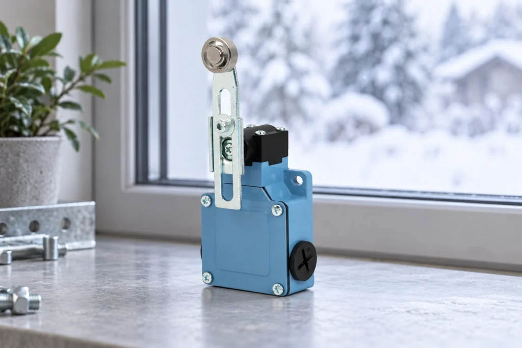
Limit switch icing must be reviewed separately from a published low-temperature limit or an ingress rating. A switch may remain within a stated ambient range while external ice prevents the roller, lever or machine target from moving as intended. Define the cold and moisture sequence, review the exact product documentation and verify the installed mechanism under representative conditions. For the LEMA LZ1 family, this guide provides application questions only. It assigns no freezing-weather rating, ice resistance or guaranteed return behavior to a particular LZ1 variant and does not authorize use outside its documented conditions. Describe how ice could reach the mechanism Begin with the installation rather than a generic winter label. Is the switch outdoors, near a cold doorway or inside equipment that changes temperature? Can water reach the actuator, target or bracket? Does the machine remain idle between cycles? The exposure sequence may be more important than the lowest weather forecast because ice formation depends on the local conditions and available moisture. The Met Office explanation of freezing rain describes one way liquid water can form ice on surfaces. It provides environmental background, not a switch test specification. An installation may also have other moisture sources or freezing sequences. Identify the conditions relevant to the actual equipment rather than assuming that every cold-weather problem is freezing rain. Record differences between operating and idle states. A moving machine may expose a different part of the actuator from a parked machine. A cover can protect one direction while allowing water from another. Photographs and an installation sketch can make those assumptions clear, but they do not establish resistance without the appropriate product evidence and verification. Dry LZ1 actuator in a winter-scene...

Lire la suite
Déclarations relatives à l’absence d’halogènes dans les interrupteurs : définir le périmètre avant d’accepter l’allégation
Blogue LEMA Électrique

Déclarations relatives à l’absence d’halogènes dans les interrupteurs : définir le périmètre avant d’accepter l’allégation

A halogen-free switch declaration needs an agreed definition, material boundary and evidence basis before it can support purchasing acceptance. The phrase alone does not identify which substances were considered, which parts were included or how the conclusion was established. For the LEMA KW7 family, request information for the complete ordered configuration and the customer's actual requirement. This article does not claim that a KW7 variant is halogen free or supply a universal numerical threshold. It explains how to turn an ambiguous environmental request into a specific, reviewable evidence record. Define the term before asking for compliance Different documents and product sectors can use halogen-content terminology within different scopes. A procurement statement should therefore name the required definition and applicable document instead of relying on a familiar phrase. The IEC Guide 122 publication addresses consistent terminology related to halogen content in IEC standards. Its existence is a reason to clarify scope, not permission to assign one threshold to every electrical component. Ask the customer whether the requirement concerns the complete switch, particular homogeneous materials, added cable or another defined boundary. Identify which elements or substance groups are covered by the requested claim and how the acceptance criteria are expressed. If the requirement comes from an internal purchasing specification, retain its revision and any customer interpretation that affects the scope. Do not copy a threshold from a printed-circuit-board material standard into an unrelated switch request without an applicable basis. A rule can be valid for its stated subject while failing to answer a different procurement question. Have the responsible customer or equipment reviewer resolve the intended definition before asking a supplier to sign a broad statement. Intact KW7 housing on a cream...

Lire la suite
CTI de l’entrée d’alimentation : faire correspondre les preuves de suivi à la matière isolante réelle.
Blogue LEMA Électrique

CTI de l’entrée d’alimentation : faire correspondre les preuves de suivi à la matière isolante réelle.

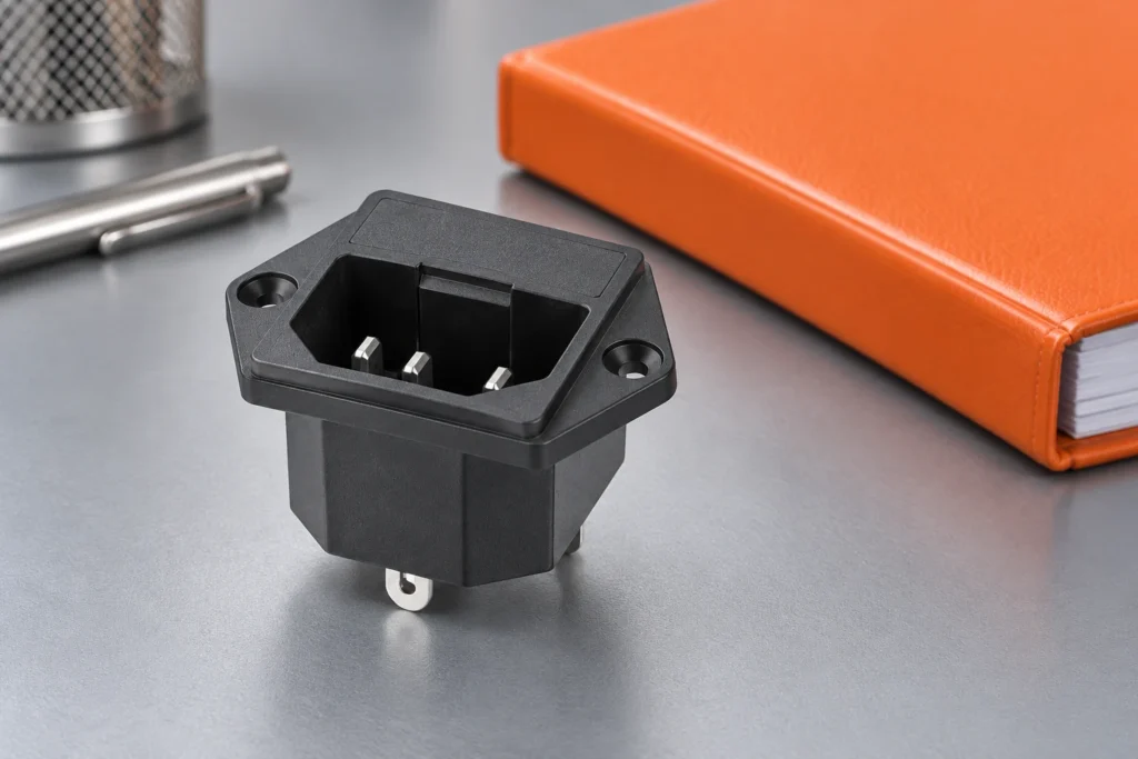
Power inlet comparative tracking index, or CTI, is evidence about the surface-tracking behavior of an insulating material under a specified test. It is not the inlet's working-voltage rating, a flame class or a universal creepage distance. Match the material record to the exact molded part, then use the applicable equipment requirements for the insulation assessment. For the LEMA IPZ family, this means requesting a documented connection between the ordered component and its actual insulating material. This guide supplies no CTI value, material group or approved spacing for an unidentified IPZ version. Understand the question CTI is intended to answer Insulating surfaces can be exposed to electrical stress and contamination under defined conditions. CTI provides a comparative material property determined by its test method. The result belongs to the evaluated material and its documented conditions. It should not be treated as a complete prediction of every surface or every installation in which that material might later appear. The UL plastics testing overview identifies electrical tracking among material-evaluation questions and references related procedures. The IEC insulation coordination publication covers clearances, creepage and solid-insulation criteria within its scope. Together these sources explain why material evidence and equipment insulation assessment are connected but remain separate tasks. Start an inquiry by asking what conclusion the equipment team needs. If the issue is an unknown resin grade, measuring an external dimension will not answer it. If the issue is a finished-assembly path, a material index alone will not close it. Naming the missing input prevents a document collection exercise from being mistaken for an engineering acceptance decision. IPZ-4 male inlet on a dark desk beside separate tools. Product-reference illustration; not a certification, laboratory result or approved...

Lire la suite
Preuves de résistance au fil incandescent de l’entrée d’alimentation : essais distincts sur les matériaux et les produits finis
Blogue LEMA Électrique

Preuves de résistance au fil incandescent de l’entrée d’alimentation : essais distincts sur les matériaux et les produits finis

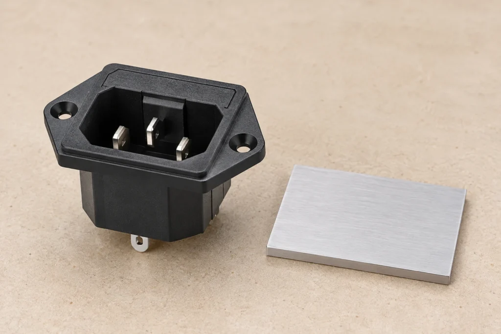
Power inlet glow-wire evidence must identify whether the result concerns a material specimen or the finished component under a defined test. GWFI, GWIT and glow-wire end-product testing answer related but different questions. A resin result or a UL 94 flame class cannot automatically be relabeled as an inlet's end-product glow-wire approval. For the LEMA IPZ family, request the exact version, material identity and applicable test documentation before making a procurement claim. This guide explains the evidence boundary; it assigns no glow-wire temperature, pass result or equipment approval to a photographed IPZ inlet. Identify the requirement before requesting a number Buyers sometimes ask for a glow-wire temperature without stating the equipment, standard or test type. That can produce a technically accurate supplier answer that addresses the wrong question. Begin with the end-product requirement and the exact component role. The responsible equipment reviewer should determine which evidence is applicable and whether further assessment is required. The UL electric ignition source overview distinguishes glow-wire end-product testing from material flammability and ignition-temperature evaluations. The UL plastics standards overview places these methods within the wider plastics-evaluation framework. These sources support a comparison of test identities; they do not provide a result for an IPZ housing or an exemption for a particular machine. Write the required evidence in the purchase specification using the applicable method and document reference. If the customer's requirement is unclear, resolve it before selecting a favorable number from a resin record. A reply saying “our plastic is flame retardant” does not identify the method, specimen conditions or finished-part boundary needed for an informed decision. Three male blades and mounting flange of an IPZ-4 inlet. Product-reference illustration; not a certification, laboratory result or...

Lire la suite
Corrosion sulfurée du micro-interrupteur : examen des preuves d’exposition des contacts
Blogue LEMA Électrique

Corrosion sulfurée du micro-interrupteur : examen des preuves d’exposition des contacts

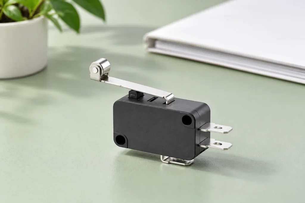
Micro switch sulfur corrosion should be investigated as a possible environmental mechanism, not diagnosed from contact intermittence alone. Establish the actual contact construction, identify plausible sulfur-bearing exposure and compare failed samples with controlled evidence before assigning a cause. For the LEMA KW7 family, obtain the exact variant's material and environmental information. This article does not claim that every KW7 contact contains silver, that a particular unit is sulfur damaged or that an enclosure eliminates corrosive gases. The goal is an evidence-based investigation that separates exposure, material response and the observed electrical fault. Start with a defined symptom and sample history Intermittent operation can arise from several sources: motion, a connection, contact behavior, wiring or the measurement system. Record what the machine did, the contact state expected and how the event was observed. Preserve timestamps and operating conditions where practical. An environmental hypothesis becomes more useful when it can be compared against repeatable observations rather than a general report that the switch is unreliable. Keep failed samples with their lot identity, location and handling history. Avoid cleaning, scraping or repeatedly cycling them before deciding what evidence is needed. Such actions can change the surface or the electrical behavior under investigation. Safe isolation and qualified handling remain necessary; preserving evidence does not mean leaving faulty equipment in operation. Use the micro switch failure investigation guide to organize alternative explanations. The present article focuses on sulfur-related exposure rather than replacing that wider diagnosis. A credible conclusion should explain why the observed evidence supports this mechanism and why the most plausible competing explanations have been considered. Intact KW7 switch on a dark blue background with no simulated corrosion. Product-reference illustration; not a certification, laboratory...

Lire la suite
Micro Switch Accelerated Life Testing: Check the Model Before Extrapolation
Blogue LEMA Électrique

Micro Switch Accelerated Life Testing: Check the Model Before Extrapolation

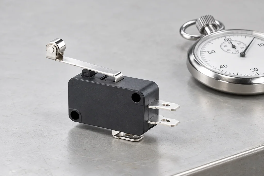
Micro switch accelerated life testing can shorten the time needed to investigate a failure mechanism, but it cannot turn an arbitrary harsh test into a credible service-life prediction. Define the intended use, identify the mechanism being accelerated and justify the relationship between test stress and service conditions before extrapolating. For the LEMA KW7 series, request evidence for the exact variant and duty. No acceleration factor, field reliability or guaranteed lifetime is assigned here. A switch that survives rapid unloaded cycling has answered a different question from a loaded switch tested under a justified acceleration model. Decide what decision the test must support Begin with the engineering decision. A team may want to compare design variants, discover weak construction, establish a qualification result or estimate life under a specified duty. These are different objectives. A test designed to expose weaknesses can be useful without supporting a numerical life prediction. Name the objective before ordering fixtures or selecting an elevated stress. The NIST accelerated life test guidance describes planning around stress levels, samples, observation time and models. The NASA accelerated testing knowledge base discusses accelerated exposure as a way to reveal failures sooner. These are general reliability resources. Neither provides a validated model or a qualified test profile for a particular LEMA switch. Write the proposed conclusion in advance. “Variant A showed fewer failures under this test” is narrower than “Variant A will last a specified number of years in every machine.” The second statement requires a chain of assumptions and evidence that the first does not. Making the intended conclusion explicit helps prevent a useful development experiment from being promoted into an unsupported sales claim. KW7 roller-lever switch beside a closed...

Lire la suite
Safety Foot Switch With Guard: Selection and Placement
Blogue LEMA Électrique

Safety Foot Switch With Guard: Selection and Placement

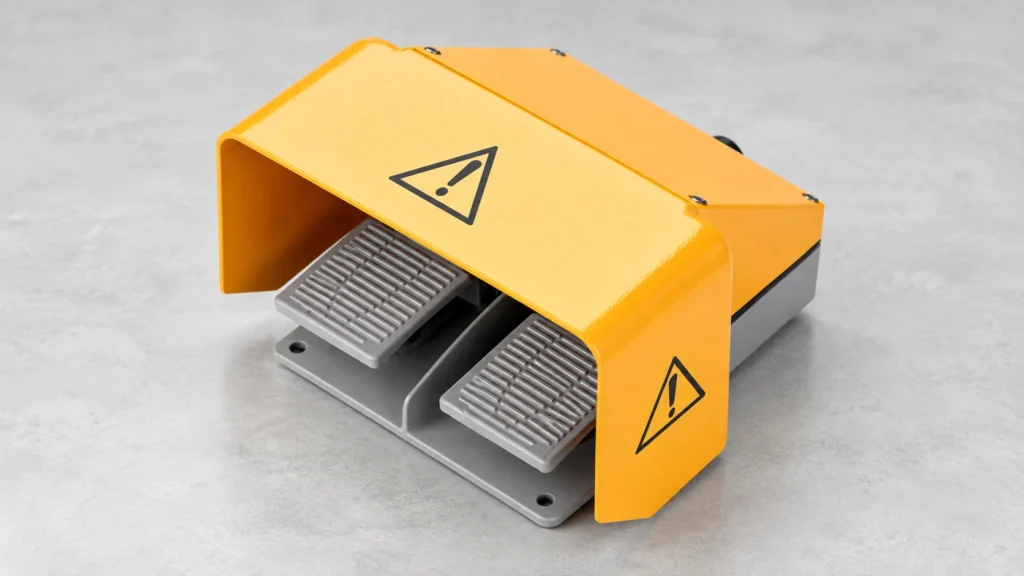
A safety foot switch is not defined by a yellow hood or a warning symbol. A guarded foot control can reduce unintended pedal activation, but safe machine operation depends on the whole system: the machine's hazards, point-of-operation safeguarding, control logic, fault response, mounting position, operator access, and validation. For a buyer comparing guarded pedals, first specify what accidental actuation the cover must resist and what intentional foot movement it must allow. Then confirm the exact pedal's mechanical and electrical details and have the machine safety function assessed by a qualified person. This guide uses LEMA's real guarded LF-series foot-switch construction as a selection example without claiming an unverified safety certification. Original LEMA LF-62 product-and-dimension image. The visible yellow hood covers two gray pedals; it is a physical guard feature, not evidence of a certified safety function. What a guarded foot switch does A foot switch lets an operator initiate or control a machine function while keeping the hands free. A protective hood or shroud can make it harder for a falling object, another person's step, or an unintended sideways movement to press the pedal. The shape, opening, side walls, and location matter: a cover that looks substantial in a catalog may still allow an object to enter from the front or a shoe to reach the pedal unintentionally. The real risk must be tested at the intended installation. For mechanical power presses, the US OSHA foot-control guidance warns that foot controls leave the operator's hands free and do not themselves separate hands from the point of operation. It also identifies inadvertent pedal activation as a hazard and calls for guarding and other safeguards in relevant press applications. That is a...

Lire la suite
6-Pin Toggle Switch Wiring: Verify a DPDT Terminal Layout
Blogue LEMA Électrique

6-Pin Toggle Switch Wiring: Verify a DPDT Terminal Layout

6-pin toggle switch wiring usually refers to a double-pole, double-throw (DPDT) switch: two independent changeover contact sets operated by one handle. Each pole has a common and two possible throws, giving six external terminals. Do not wire a switch from the pin count or a generic photograph alone. Identify the exact model and its ON-ON, ON-OFF-ON, momentary, or other action; then test the de-energized terminals for continuity in every handle position. Only after that map should a qualified person connect a circuit that fits the switch's ratings and the equipment's protection design. This guide focuses on terminal identification and verification, not an untested universal pinout. Original LEMA LT2220C product photo. Six flat terminals can be inspected from this angle; their functional mapping must still be verified from the exact drawing and continuity test. What six terminals mean—and what they do not A DPDT toggle is functionally two SPDT changeover contacts moved together. Pole A and pole B are electrically separate until an external circuit connects them. Each pole has a common terminal that connects to one throw in one position and the other throw in the opposite position. The switch can route two independent signals, or be arranged for another appropriate application after the circuit designer verifies ratings and fault behavior. Six terminals do not reveal which physical lug is common on a particular model, and they do not reveal whether the center position is OFF. The City Tech electronics lab manual treats a DPDT as a two-state input and explicitly tells students to check continuity because a real switch can differ from the illustrated pattern. A South African Department of Basic Education learner book explains a DPDT as two...

Lire la suite
Micro Switch Electrical Life vs Mechanical Life: What the Ratings Mean
Blogue LEMA Électrique

Micro Switch Electrical Life vs Mechanical Life: What the Ratings Mean

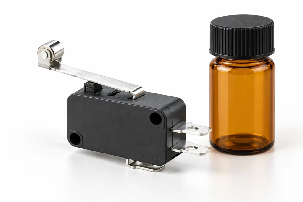
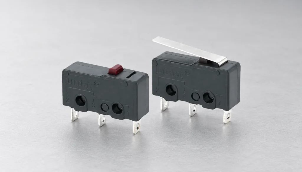
Micro switch electrical life vs mechanical life compares two different endurance tests. Mechanical life counts operations at a stated speed and travel without an energized contact load. Electrical life counts operations while the contacts switch a specified voltage, current, and load type. The figures are not interchangeable, and neither is a calendar-life promise for a finished machine. A buyer should ask for the exact model's test conditions, then compare them with the machine's real actuation rate, overtravel, inrush, duty cycle, environment, and acceptable failure risk. This guide explains how to read those figures without inventing a life rating for a LEMA part that has not been tested in your assembly. Original LEMA KW12-series product photo. The plunger and lever affect how the switch is operated; the image itself does not establish a cycle-life rating. What is mechanical life? Mechanical life, also called mechanical durability, describes the number of full switch operations achieved under a stated mechanical test, normally with the contact circuit not energized. An operation means the actuator is moved through its specified operating and release sequence, not merely touched. The test must define operation frequency, stroke or overtravel, operating speed, mounting, and the criterion used to call the switch failed. A mechanism can lose its snap action, spring force, return behavior, or dimensional stability even if no electrical load is switched. The IEC 61020-1 publication description identifies electromechanical switches as devices that change an electrical connection through mechanical contact motion and says the generic specification addresses terminology and test methods. That is a useful framework, not evidence that any particular KW12 model meets a specific endurance value. For the mechanical side of a purchased model, request the manufacturer's...

Lire la suite