
A limit switch can change its electrical state when a machine target reaches the actuator, yet the machine may continue moving for some time afterward. That is why “limit switch response time” and “machine stopping distance” are not the same measurement. The first concerns a switch or signal stage; the second depends on the complete control path and the moving machine.
This guide separates the stages, shows how to estimate delay-related travel, and explains what must be measured before using the result in a machine design. No generic millisecond value applies to every limit switch or machine. Use the exact switch data and a qualified measurement of the installed system. A general-purpose limit switch should not be treated as a safety-rated protective device unless the device and complete safety function are specifically designed and validated for that purpose.
What does limit switch response time mean?
In everyday use, response time may refer to the interval from mechanical actuation until the contacts change state, until a controller registers the input, or until the driven machine stops. Those endpoints describe different events. If a supplier publishes an operate or release time, check its test conditions and the exact model. Many mechanical limit-switch selection guides instead specify operating speed, operating frequency, travel and contact characteristics; those values are not automatically a complete machine response time.
For a moving mechanism, define at least three timestamps: when the target first contacts the actuator, when the electrical input changes state, and when the hazardous movement has actually stopped. The interval between the first two is a switch-and-input question. The interval between the first and last is a system and machine question. Keep the definitions consistent when comparing measurements.
Omron’s limit-switch technical guide advises checking operating speed and switching frequency, notes that extremely high operating speed can damage a switch through shock, and explains that actuator profile and travel after operation affect accuracy and durability. These are important mechanical operating limits, but they do not provide a universal stopping-time value for a machine.
The full delay chain determines travel after actuation
A typical position-control chain may include the actuator moving through its operating travel, contact transition, input filtering, remote-I/O update, controller task or scan, logic, output module, relay or contactor, drive response, brake build-up and mechanical deceleration. The actual arrangement varies. A direct relay circuit has a different path from a networked controller and variable-frequency drive.
| Stage | What to identify | How it can affect the result |
|---|---|---|
| Target and actuator | Target approach, operating position, overtravel, bounce, mounting flex | The target may travel before a stable input is available; excessive impact can damage or misoperate the switch. |
| Switch contacts | Exact model, operate/release behavior, contact form and rated switching frequency | Contact transition and mechanical settling are model- and application-dependent. |
| Input and logic | Input filter, remote-I/O update, scan/task period, network and logic path | The controller may not act at the instant the physical contact changes. |
| Output and drive | Output update, relay/contactor delay, drive stop mode, brake timing | A stop command is not the same event as torque removal or braking force taking effect. |
| Machine mechanics | Speed, load, inertia, friction, brake condition, backlash and travel direction | The machine may coast or decelerate differently as operating conditions change. |
A useful first-order estimate for the distance travelled during a known signal delay is ddelay = v × t, where v is the machine’s speed during that delay and t is the measured delay in matching time units. If a simplified constant-deceleration model is appropriate, the idealized braking distance is dbrake = v² / (2a), where a is the deceleration magnitude. These equations explain why delay and speed matter; they do not replace a machine stop-time measurement, a risk assessment or a safety-distance calculation.
Why a machine can overrun its limit position
The sensor may be only one contributor. A long input filter, slow controller task, I/O network cycle or output relay can add delay after the contact changes. A motor may coast after power is removed, while a brake may need time to engage. A heavy or gravity-loaded mechanism may behave differently from an unloaded bench test. Backlash, flexible brackets, target geometry and actuator overtravel can add mechanical travel before or after the input transition.
Switch adjustment matters too. A roller lever that is struck abruptly may bounce or receive more force than intended. Mounting the actuator close to its operating point or overtravel limit can create unstable behavior or damage. Omron’s guidance calls for checking speed and switching frequency and keeping actuator travel within the model’s permitted range. Select an actuator and target profile for the motion, then verify the installed geometry over its tolerances.
Contact bounce and input filtering should be considered together. Filtering may reject short transitions, but increasing a filter to hide chatter also delays recognition of a real transition. Do not “fix” inconsistent signals by arbitrarily increasing filtering; inspect alignment, vibration, contact condition, wiring, grounding and the controller’s input design.
How to measure the installed stop time
- Define the event and endpoint. State whether the measurement starts at target contact, switch contact transition or controller input, and whether “stopped” means zero speed, brake engaged or motion within a specified tolerance.
- Use the right measurement equipment. For machinery where stopping time affects safeguarding, use a suitable stop-time measurement method and follow the machine and safety-device manufacturer’s procedures. OSHA describes measuring the stop time at the machine’s final control element when determining safety distance for covered press applications.
- Test the real configuration. Include the selected switch, wiring, filters, I/O, program, output device, drive, brake, load and mechanical transmission. A bench test of the switch alone cannot represent this chain.
- Check relevant operating conditions. Measure under the machine’s validated worst-case conditions, such as appropriate speed, load, direction, temperature and brake condition. Follow site safety procedures and keep people outside hazardous zones.
- Repeat and record. Record the model, software and drive settings, equipment state, test method, observed time and distance, and variation between trials. Re-measure after changes that can affect the stop path.
Do not deliberately defeat a guard or place a person in a danger zone to obtain a measurement. Stop-time verification is an engineering and safety task; have a competent person plan and perform it with the proper equipment and controls.
Do not turn a limit-switch time into a safety-distance shortcut
OSHA’s machine-guarding guidance explains that total response time for a safety-distance calculation can include machine stopping time, control-system response, the presence-sensing device and its interface, plus applicable brake-monitor allowance. The specific formula shown on OSHA’s page applies to mechanical power presses and related safeguarding context; it should not be copied as a universal formula for every limit switch or machine.
A standard position limit switch can be part of ordinary machine control, but it is not automatically a personnel-protection function. Where people can reach a hazard, select safeguards and safety controls through the applicable risk assessment, standards, validated architecture and machine-specific stopping data. A limit switch’s contact rating, IP code or fast mechanical action does not prove that the complete system is suitable as an emergency stop or protective interlock.
For further reading, see the OSHA safety-distance and stop-time guidance, Omron’s technical guide for limit switches, and Pilz’s stop-time measurement webinar. These references explain system-level considerations; the applicable requirements depend on the machine and jurisdiction.
Select and mount the switch for the motion
Choose the actuator style for the target path: a plunger, roller plunger, lever or roller lever behaves differently under side load and approach direction. Check the exact model’s operating position, pre-travel, overtravel, release position, differential travel, operating speed and maximum switching frequency. Avoid using the actuator as a mechanical end stop unless the manufacturer explicitly permits that use.
Place the switch so the target operates it consistently and leaves the required travel margin. Use a smooth cam or dog, rigid mounting, suitable fasteners and accessible adjustment. Verify that the moving target does not strike the lever end-on or force the actuator beyond its allowed range. A different roller diameter, lever length, mounting orientation or bracket stiffness can change the observed actuation point and wear pattern.
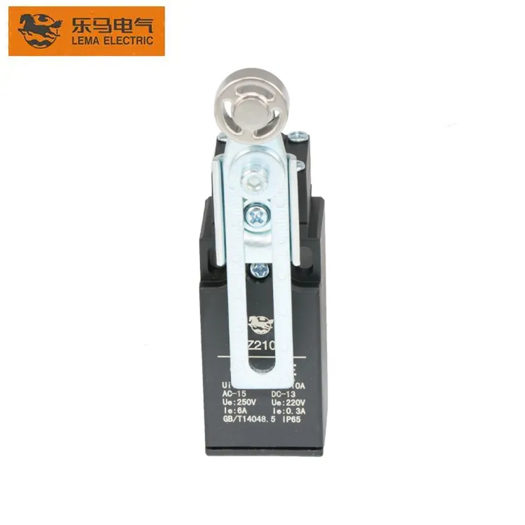
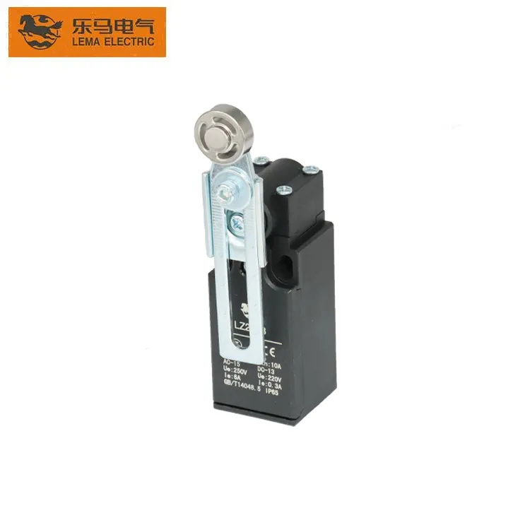
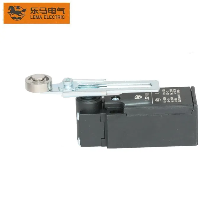
The LEMA LZ2108 product page is the model-specific reference for the roller-arm switch shown here; use its published documentation rather than estimating dimensions from a photo. Browse the limit switch category and compare this topic with the guides to mounting position and repeatability, limit switches vs proximity sensors and hoist limit-switch overtravel.
Common questions
How fast does a limit switch respond?
There is no single value for all limit switches. Use a published operate/release time only when it is specified for the exact model and conditions. For machine motion, measure the complete input-to-stop chain.
Is limit switch response time the same as stopping time?
No. Switch response concerns a switch or signal transition. Stopping time includes the control path and the machine’s deceleration until the defined stop condition is reached.
How do I calculate distance travelled after a limit switch changes state?
For a simple delay estimate, multiply speed by measured delay. Braking adds further travel. Use a suitable machine-specific measurement for design and safety; a simplified equation is not a validated safety calculation.
Can a standard limit switch be used as an emergency stop?
Not by assumption. Use a suitable safety function and validated system selected through the machine’s risk assessment and applicable requirements.
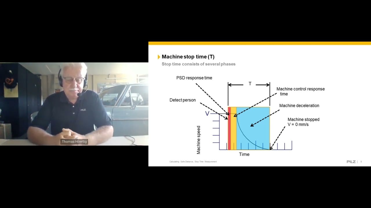
Video: measuring machine stop time
This Pilz training webinar explains stop-time measurement and safety-distance concepts. It is general educational material, not a substitute for machine-specific validation or the applicable standard.
External references: OSHA machine-guarding safety distance and stop-time measurement; Omron Technical Guide for Limit Switches; Pilz stop-time measurement webinar.