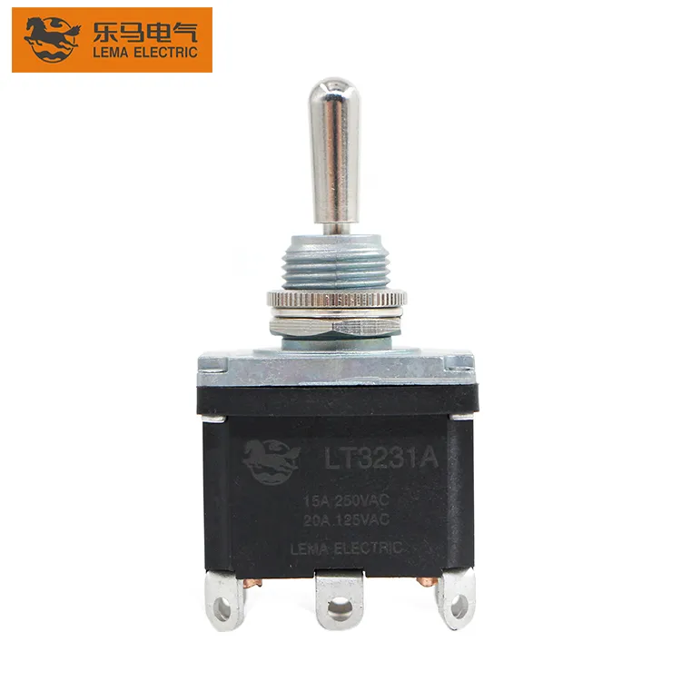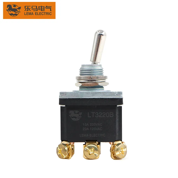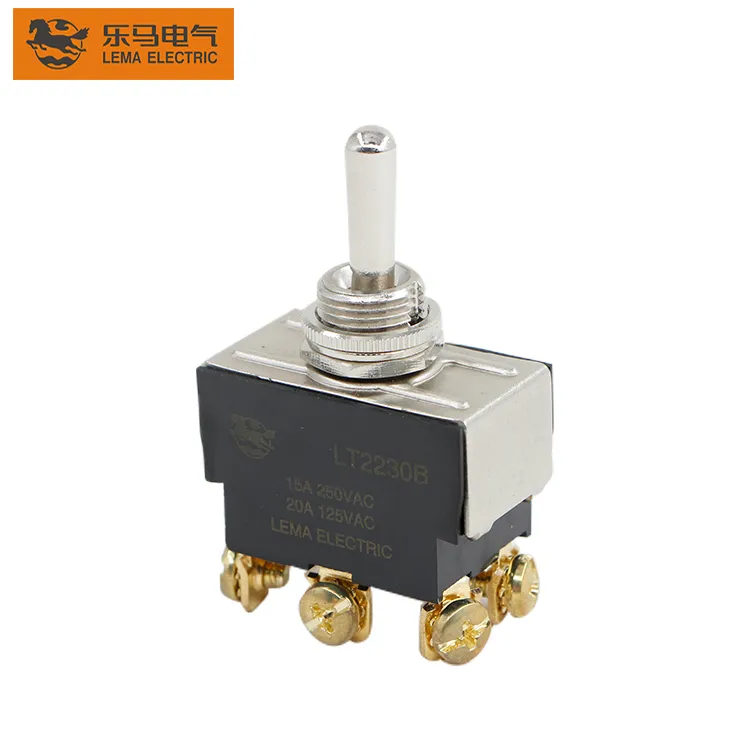
Integrating an Illuminated Toggle Switch Into an OEM Panel
An illuminated toggle adds a second communication circuit to the panel. Decide what the indicator means, where it is sourced, and how service verifies it before the design team releases the harness. Important: an illuminated appearance does not establish a lamp or LED voltage, current rating, ingress result, approval or life. Confirm every model-specific limit in the selected documentation. Source note: IEC 61058-1 publication scope and selected-model documentation. - FAQ ContentsPart 1. What does illumination add to a toggle circuit?Part 2. Which source and state inputs belong on the drawing?Part 3. How should indicator terminals and harness routing be controlled?Part 4. How do panel legends and service visibility affect the design?Part 5. Why must the indicator remain separate from load assumptions?Part 6. What should be validated before sample approval?Part 7. How can LEMA support an illuminated-toggle inquiry?Part 1. What does illumination add to a toggle circuit? The indicator communicates a chosen condition to an operator; the switch contacts control a circuit. Those conditions may align, but they must never be assumed to be identical. Capture whether the legend should show source availability, a selected state, an active load, or a fault-related condition, then build the drawing around that decision. Decision fieldRecord in the packageSend with quoteMeaningWhat the panel indication representsYesSourceWhere the indicator circuit is fedYesStateWhich circuit state is intended to be visibleYesServiceLegend, test point and replacement pathYes Begin product-family navigation at the LEMA Toggle Switch product line after those inputs are written. Part 2. Which source and state inputs belong on the drawing? Show the main load path and the indicator path separately. A source-powered indicator can communicate panel availability while a load-following indicator can communicate a switched condition; the...
Read More